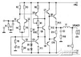
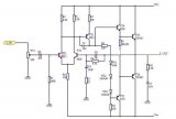
[Photo] Current feedback power amplifier circuit
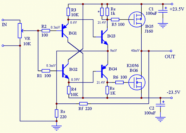
The working principle of the circuit is: the input signal voltage is converted into a current by a buffer of gain 1 (BG1, BG2), and then converted into a voltage by an IV converter (BG3, BG4), and then further amplified by BG5, BG6 to drive the load . After the feedback resistance Rf converts the output voltage into a current, it is added to the emitter resistance Rs of the IV converter to form a current negative feedback. Therefore, the current flowing through Rs is the difference between the current of the IV converter and the feedback current. Circuit gain Kf = 1 + Rf / Rs
Since the input buffer is not included in the feedback loop, special attention should be paid to the performance of this stage. Here, the Darlington tube combination method is adopted between the input buffer and the IV converter, and the highly acclaimed NEC pair tube 2SA992 / 2SC1845 is selected to obtain higher input impedance and lower output impedance, and the overall performance ratio Other combination methods are superior and the structure is simple. The output stage uses Hitachi's high-power MOS-FET 2SK1056 / 2SJ160 (its symmetry is better than other FETs), and connected into a common source push-pull amplification method, eliminating the output buffer, further simplifying the circuit.
In current feedback amplifiers, the value of the feedback resistor Rf cannot be too large, and should generally be <1KΩ. This circuit only takes 220Ω. The value of Rs is related to the degree of distortion, frequency bandwidth and circuit gain. Here, 22Ω gain is about 20dB, and the feedback amount is about 30dB, which can get better overall performance. The circuit's square wave is excellent, the conversion rate is as high as 412V / uS, the output power is 25W, the distortion at this time is <0.5%, and the damping coefficient is DF = 17. The circuit has a high degree of resolution and clear and transparent sound. Even if it is connected to a 1uF pure capacitive load, it can work stably, reflecting the characteristics of current feedback power amplifier.

Follow WeChat

Download Audiophile APP

Follow the audiophile class
related suggestion
This article mainly introduces the 807 tube power amplifier circuit diagram (a detailed explanation of ten analog circuit design schematics). FU-7 (807) high power electronic ...
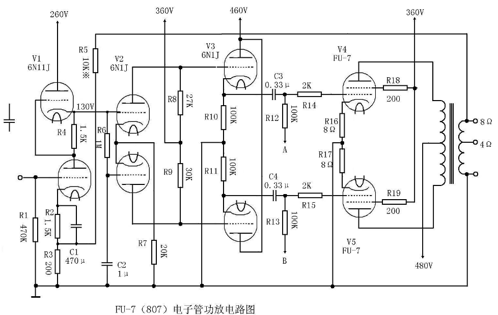
This article mainly introduces the 211 tube power amplifier circuit diagram (a detailed explanation of the eight analog circuit design schematics). 211 is a high-power direct-heating three-pole power amplifier ...
This article mainly introduces the collection of 3dd15d power amplifier circuit diagrams. Use computer audio signal to input mono, according to different power supply voltage, actually measure music output power ...
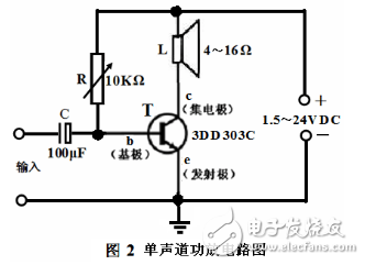
This article mainly introduces the simple audio power amplifier circuit schematic diagram (six simple audio power amplifier circuit design schematic diagram in detail). OPA5 mentioned in the scheme ...
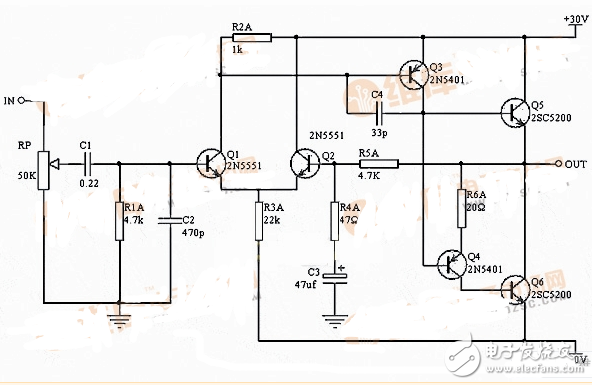
This article mainly introduces the simplest single differential OCL power amplifier circuit diagram (four single differential OCL power amplifier circuit design schematic details). cL power amplifier circuit ...
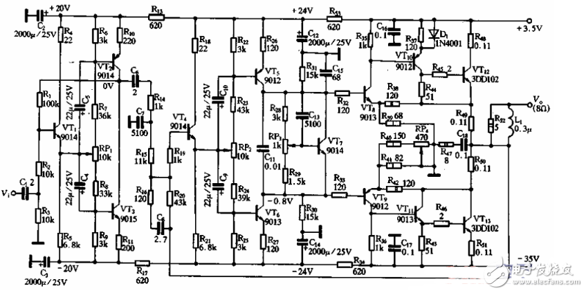
This article mainly introduces the circuit diagram of the fully symmetric ocl power amplifier (the schematic diagram of the design of four fully symmetric ocl power amplifier circuits) The power amplifier in the scheme adopts all pairs ...
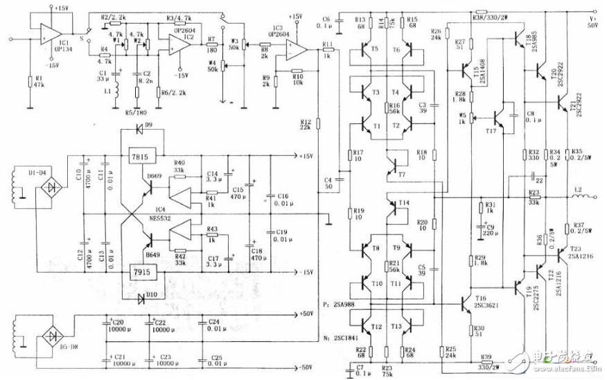
This article mainly introduces the power amplifier circuit diagram series two (detailed analysis of the principle of each type of power amplifier circuit diagram). The bias of the class B amplifier makes the push-pull transistor work ...
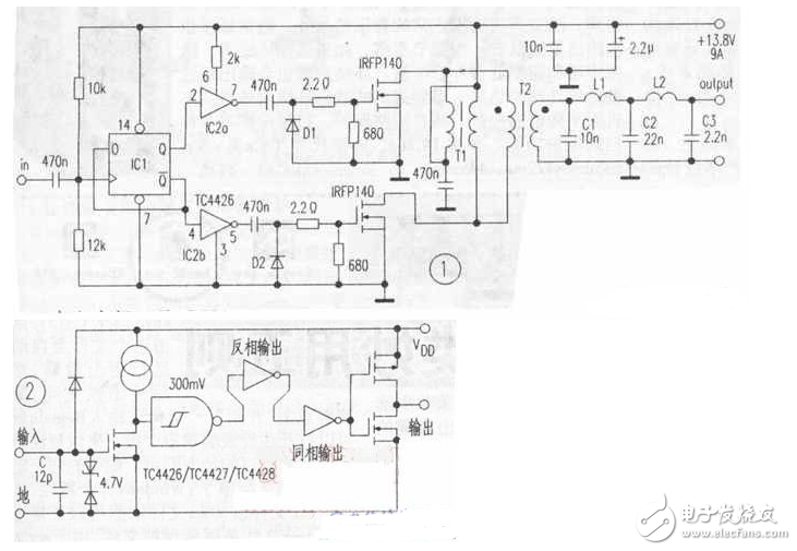
Ic1 selects the double D flip-flop CD4013. IC2 selects high-speed MOSFET drive circuit TC4426, the chip is at 4.5V ...
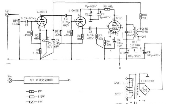
This article mainly introduces the simplest 12v power amplifier circuit diagram (four kinds of power amplifier circuit diagrams in detail). The power amplifier circuit is a kind of purpose for outputting larger power ...
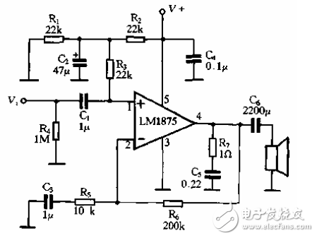
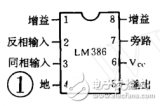
Introduction of LM386 LM386 is a kind of audio set successfully, with low power consumption, adjustable voltage gain, large power supply voltage range, external components ...
tda2822m is a dual-channel monolithic power amplifier integrated circuit developed by STMicroelectronics (ST), usually in a pocket cassette player (WAL ...
uPC1225H is a 50W audio driver circuit launched by NEC. The chip is equipped with perfect protection links, although the peripheral circuit is slightly complicated ...

In the field of audio, people have always maintained the position of Class A amplifiers. It is considered that the sound of Class A amplifiers is the most fresh and transparent, with high fidelity. However, Class A ...

This article shares a detailed step-by-step DIY of the assembly of all-digital audio power amplifier circuit, the required materials and the functions of desktop speakers, etc.

OCL power amplifier circuit has been widely used by various manufacturers for a long time due to its superior performance and high stability and reliability. But due to various ...
The microphone power amplifier circuit is made based on TDA2822, and a dual-channel audio amplifier integrated circuit is used. Its main features are high efficiency, low power consumption, static work ...
Introduced the characteristics of the digital power amplifier TDA8902J and its circuit application, analyzed the selection of the main components of the power amplifier peripheral circuit, and ...
In transistor receivers and amplifiers, push-pull power amplifier circuits are widely used. Traditional push-pull circuits always require input transformers and output transformers.
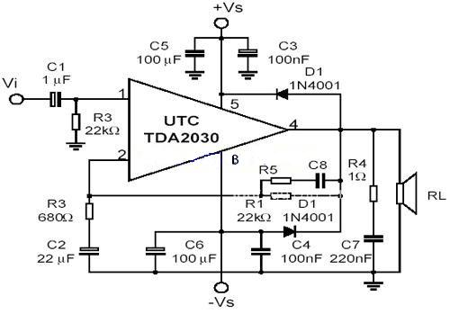
TDA2030 adopts V-shaped 5-pin single in-line plastic packaging structure.
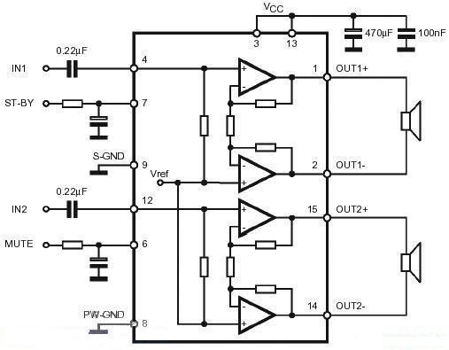
TDA7266 is a dual audio stereo amplifier, packaged in MULTIWATT format, specially designed for high quality of music equipment and color TV ...
As shown in Figure 2A3A is a low internal resistance direct thermal triode, its internal resistance is only 800, so the output impedance of the side-to-screen load impedance is 3.5k. ...

6KD6 pentode OTL power amplifier circuit diagram explanation and explanation: 6KD6 is to change the ordinary beam radiating quadrupole or pentode power electron tube to the triode connection ...

The electronic enthusiasts network provides you with the tube Zell / ZELL power amplifier circuit, I hope to help you!

In order to solve the problem of low volume of DM500 pick-up, it was decided to solve this problem fundamentally-increase the power amplifier circuit in the machine.

The electronic enthusiast website provides you with a karaoke amplifier circuit diagram. There are other amplifier circuit diagrams on this site. I hope you can learn from the amplifier circuit diagram ...

Pin 10 and pin 12 of the TA2020 chip are audio input pins. It is strictly forbidden to have a DC input, otherwise it will affect its static operating point, and the input terminal must be coupled ...

Electronic enthusiasts network provides you with the audio power amplifier circuit composed of MCl351, there are other related resources on this site, I hope to help you!

The electronic enthusiast network provides you with a single power amplifier circuit composed of LM4781. There are other related resources on this site. I hope to help you!

Although the use of electron tubes in modern electronic technology applications has been less, but due to some superior characteristics of irreplaceable transistors, electron tubes ...

Electronic enthusiasts provide you with two schematic diagrams of the power amplifier circuit of the negative pressure mode of the fixed gate of the tube, and hope to help you!

Here I want to introduce you to the production of a truly balanced BTL bridge power amplifier. This amplifier can directly input the balance of XLR ...
Debugging method Before debugging, check the components as usual. Whether the installation and welding are correct and reliable. Pay special attention to the polarity of diodes, transistors, electrolytic capacitors ...

The working voltage of the base of the input pole (9014) is equal to the midpoint voltage of the two output pole transistor, which is generally half of the power supply voltage.

This split-type pure class A power amplifier places the voltage amplifier and 0dB power output stage in two chassis, which avoids the phase between the two ...
TDA1521 pin function and reference voltage: 1 pin: 11V-reverse input 1 (L channel signal input) 2 pin: 11V-positive ...

The utilization rate of the power supply of the bridge type push-pull power amplifier circuit diagram (ideally) is 100%, which is 50% higher than the OTL or OCL circuit.

Professional power amplifier circuit protection part

It is also required that the power transformer has two filament windings, and the power stage and the previous stage filament are supplied separately. The circuit is an experiment made with 6Pl, although the gate negative pressure is lower ...

According to the requirements of different power tubes for negative grid voltage, different voltage division values ​​can be taken. This circuit is suitable for various power tubes. The filament ground of the two tubes in the circuit, ...

Only one amplifier is drawn in the circuit. Mainly to reflect the special form of power supply. The circuit has good experimental results, and the first-level voltage amplification can also output one watt left ...

The power amplifier can be powered by 220V city power or 12V battery. The power amplifier takes up very little space, the power is moderate, and it is convenient and practical. ...
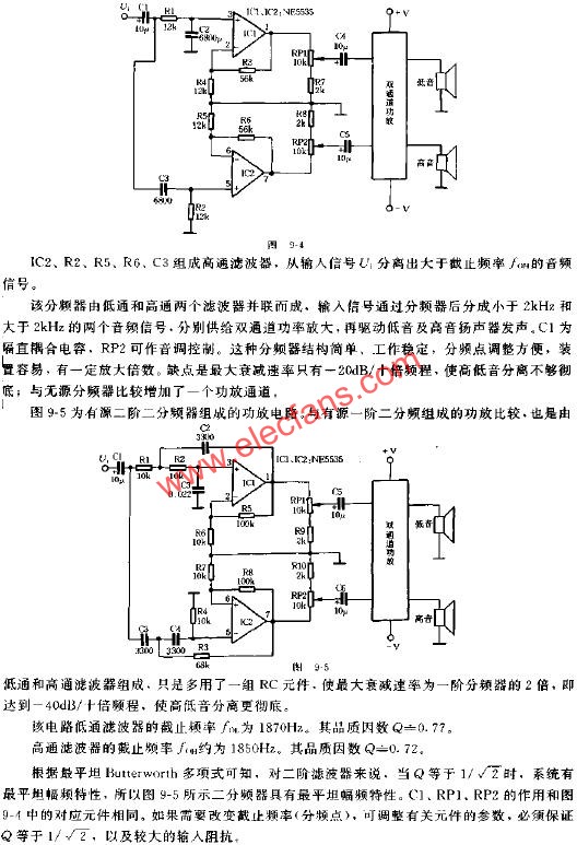
The use of an active frequency divider can reduce the bandwidth requirements of the power amplifier; the high-power LC components are eliminated; the frequency division point is also easy to adjust, and the specific power can be obtained
Circuit principle: This field effect tube power amplifier is suitable for those who are obsessed with the sound of the tube, so they can't make a good sound for the post-amp; ...
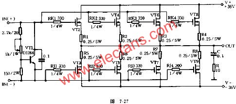
The rated power 100W * 2 super-class DC field effect tube power amplifier introduced in this article has large output power, wide frequency response, good sound quality and stable performance ...
There are a lot of enthusiasts who admire motorcycles nowadays, but after all, there is a "barrel" effect on motorcycles, and the effect is not very satisfactory. It is better to choose than to "make up"
I have a few idle LM317Ts in my hand. I heard that some people use power amplifier ICs as voltage stabilizers, so I wondered if I could use voltage regulator ICs as power amplifiers. ...
Circuit principle: The circuit is shown in the figure below, and the tone circuit is selected from the US LM1036.

The dual operational amplifier NE5532 has the characteristics of fine tone and transparent treble, so it is used by many audio enthusiasts Zhongman, and it is made of a fully parallel power amplifier ...
Circuit principle: The power amplifier introduced in this article only uses more than 20 components. Circuit (left and right channels
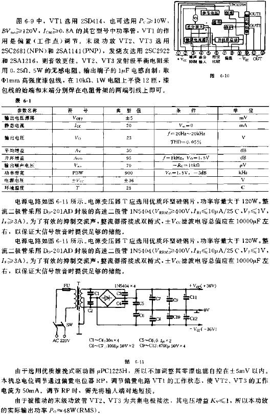
This article introduces an audio amplifier with large output power and good performance. It includes pre-control circuit and power amplifier circuit. Choose Toshiba's TD ...
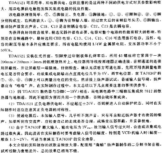
So far, almost all high-fidelity power amplifiers have been designed to have flat frequency response characteristics. However, due to the
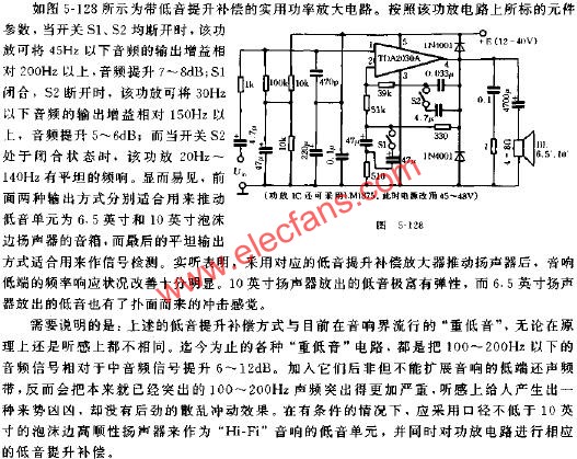
A simple circuit that reproduces high-quality sound is a tireless pursuit of many audio enthusiasts. This circuit is based on this point, with a simple circuit replay ...
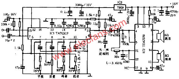
Generally, the integrated circuit has many peripheral components and requires a large heat sink. The power amplifier circuit introduced in this article is simple and easy to make.
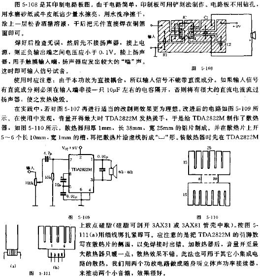
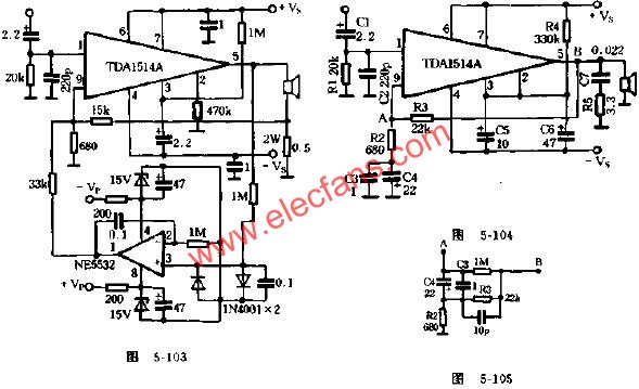
A few days ago, I purchased a printed circuit board of a DC servo constant current stereo power amplifier from a company. It uses TDA1514A integrated circuit, as shown in Figure 5 -...
For audio enthusiasts, it is indeed a great pride to be able to make a high-quality power amplifier by yourself. Let me introduce you to an actual production ...
Circuit principle: From the well-known, the large loop feedback from the power amplifier output stage to the front stage can improve the frequency of the amplifier
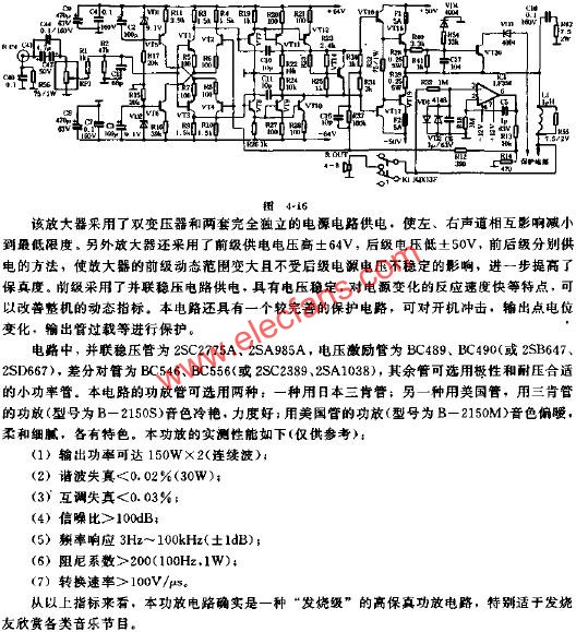
In this paper, a WDB228 Class B power amplifier is used to "move" to make it a current negative feedback amplifier. The sound quality is very satisfactory. ...

In many fever articles in recent years, conciseness has always been a topic that many enthusiasts talk about. The following is just such a simple circuit ...
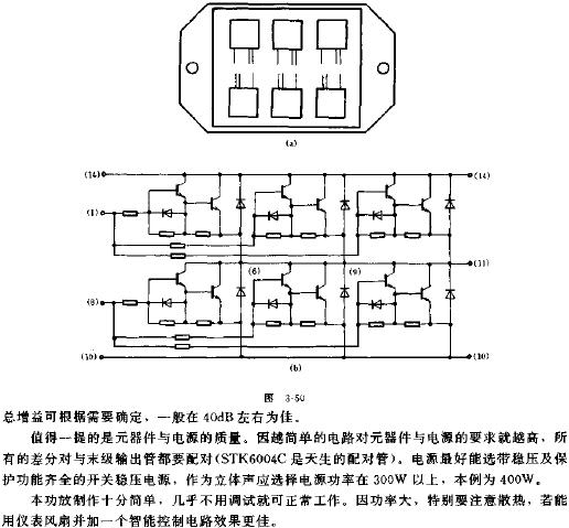
This article introduces a kind of pre-amplification thick film circuit STK3048A (IC1) as a driving stage, power amplification thick film circuit STK6153 (I ...
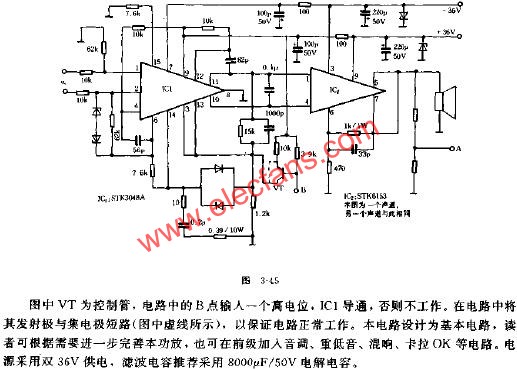
This article introduces a small power amplifier with op amp Huang Shi beautiful and direct coupling, which is a good product for this fever. Circuit principle:
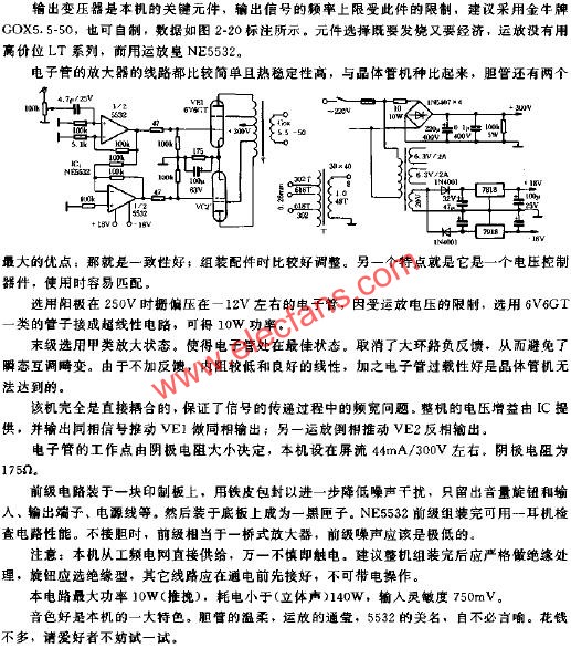
The principle of this amplifier push-pull power amplifier is shown in the figure. The two DC circuits of the output stage are connected in series, and the AC circuits are connected in antiparallel. Each component constitutes a
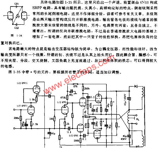
Circuit principle: 811A is a typical direct thermal triode, the cathode material is thorium tungsten carbide, similar to Liangdan 805
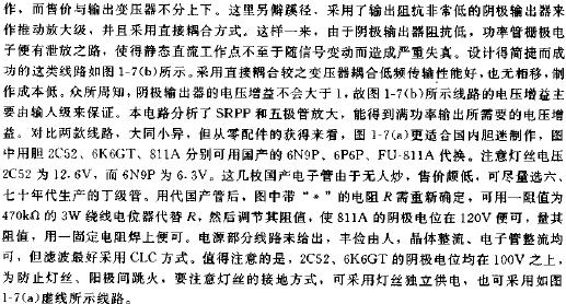
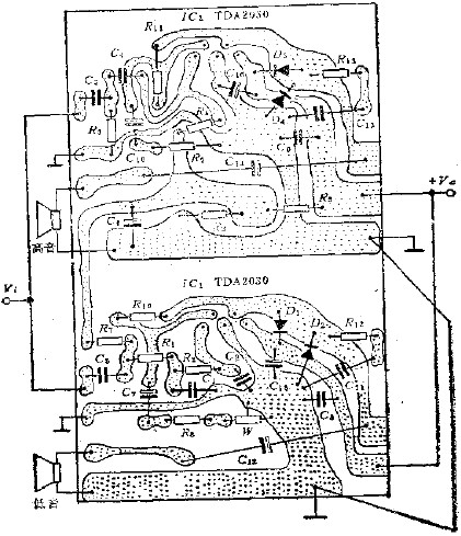
TD2030 is a power amplifier integrated circuit with very good performance.At present, many well-known large companies in Western Europe such as France's Moson Company, Italy SG ...
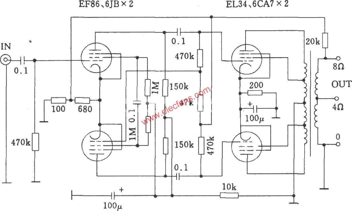
Tube QUADll power amplifier circuit diagram
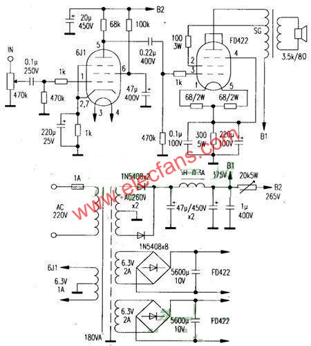
The author chose FD422 tube (direct heating type of FU7 tube) to make a Class A single-ended amplifier
The Class D amplifier circuit produced by CA3160 is shown in Figure 1. This is a phase-locked loop CD4046 and TW ...
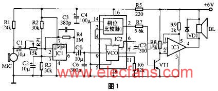
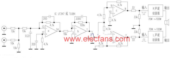
This circuit is suitable for the use of discrete components or integrated circuit mono power amplifier, BTL output can be composed without changing a component. The principle is very simple, that is ...
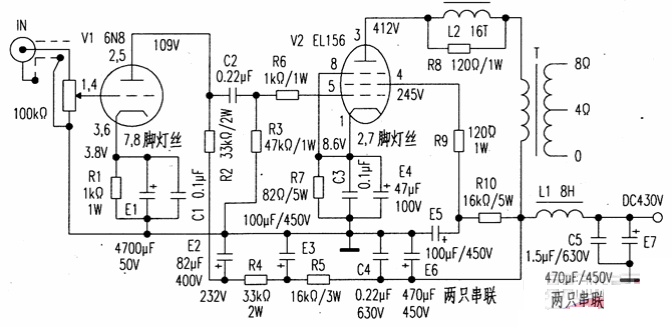
Using 6n8P + EL156 self-made tube power amplifier circuit The following picture is adopted ...
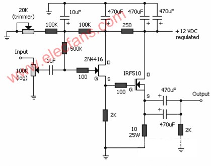
JFET-MOSFET headphone amplifier circuit
Simple and practical three-pole power amplifier circuit Simple and low cost. The optimal supp ...
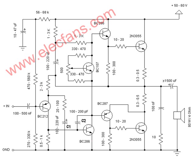
50Watt Amplifier Circuit (50Watt Amplifier) ​​This is a handy, eas ...
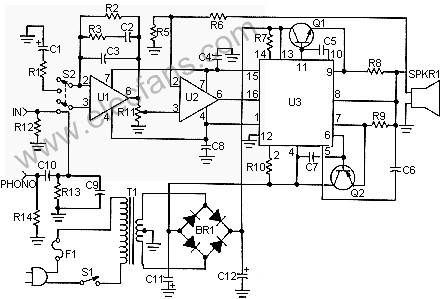
Linear FM 50Watt with BLY90 50W FM FM power amplifier circuit ...
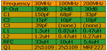
1W FM Transmitting Power Amplifier Circuit Made with 2N5109 Transistor
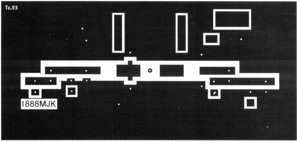
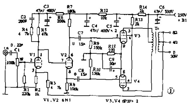
The debugging-free last typical power amplifier circuit is shown in Figure 1. V1 and V2 are a domestic-made voltage-amplified double tri-sensitive tube BN1. v ...
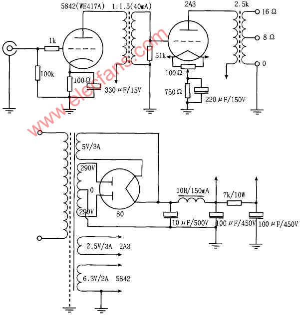
Simple 2A3 (2A3SE-4W) single-ended power amplifier circuit
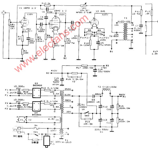
845 single-ended power amplifier circuit diagram 1.
6N3 + LM4780 power amplifier production and circuit are as follows. The

2 × 100W high-fidelity dual-channel power amplifier
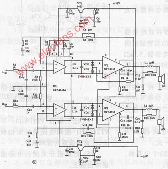
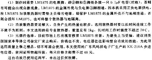
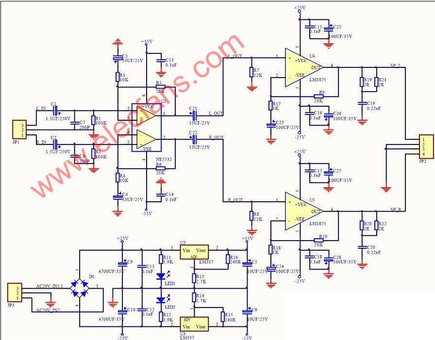
lm1875 + ne5532 power amplifier circuit
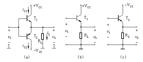
The Class B complementary symmetrical power amplifier circuit works on the Class B amplifier circuit. Although the tube consumption is small, it is conducive to improving efficiency, but there is serious distortion, which makes the input ...
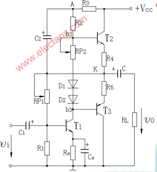
Practical OTL power amplifier circuit features: simple circuit, high efficiency, good low frequency response, easy to integrate; but the output waveform produces distortion near zero-crossing ...
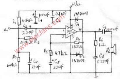
tda2006 single power amplifier circuit
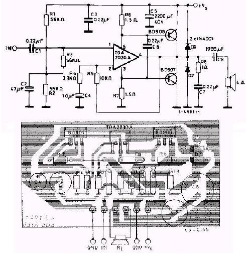
TDA2030 power amplifier integrated block and 40w power amplifier circuit made by BD907 / BD908
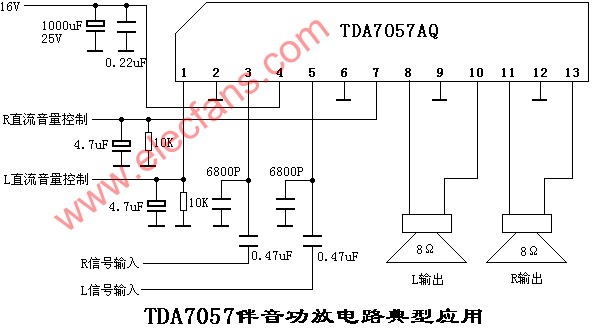
TDA7057 / TDA7057AQ sound power amplifier circuit diagram
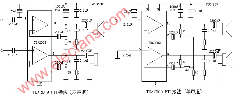
TDA2009 OTL single / dual channel power amplifier circuit diagram
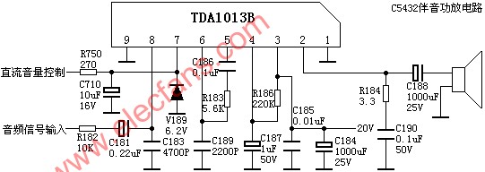
TDA1013 sound amplifier circuit
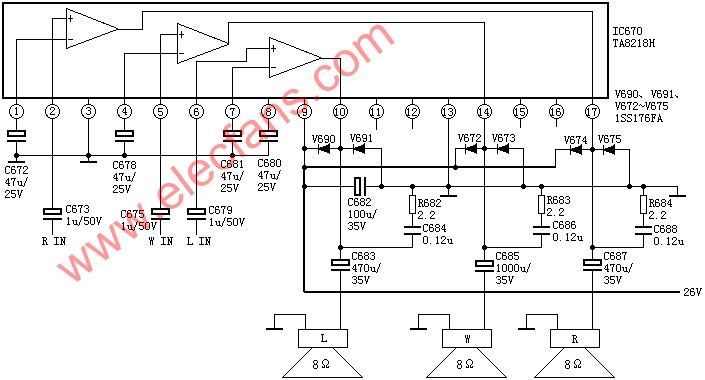
TA8218 / TA8218H three-channel power amplifier circuit diagram
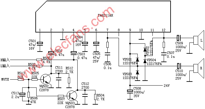
TA8211 / TA8211AH dual-channel power amplifier circuit
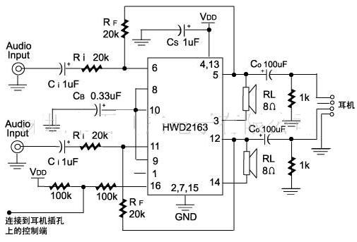
Audio power amplifier circuit HWD4863, HWD2163 DIP / SOP16 TSSOP20 package. Output power: 2 ...
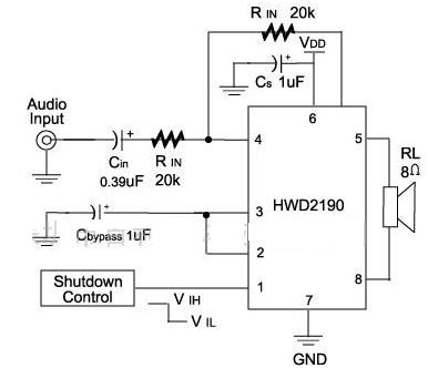
HWD2190 power amplifier circuit diagram
