Design of Bus ABS Controller Based on MC9S12DP256B
The anti-lock Brake System (ABS) is used to prevent the wheels from being completely locked during the braking process of the car, improve the directional stability and steering ability of the car during braking, and shorten the braking. distance. For the automotive anti-lock braking system (ABS), the internationally popular control methods include logic threshold control, PID control, sliding mode variable structure control, optimal control, fuzzy control and neural network control. The control method adopted by ABS in China is mainly the most basic logic threshold control method. At present, there are many research institutes in China that study ABS theory. Some representative ones are: State Key Laboratory of Automotive Dynamic Simulation, represented by Academician Guo Konghui, State Key Laboratory of Automotive Safety and Energy, Tsinghua University, South China Institute of Technology and Transportation Automobile Department, Jinan Chengjun Electronic Technology Company, etc. There are many domestic ABS companies, but most of them are produced in cooperation with famous foreign ABS companies. Their products are not independently developed. The more representative domestic companies that have completely developed ABS are Chongqing Juoneng Automotive Technology Co., Ltd. and Xi'an Bohua Electromechanical Co., Ltd. [1].
This article refers to the address: http://
During the braking process of the car, the wheel may slip relative to the road surface, and the proportion of the slip component in the longitudinal movement of the wheel may be characterized by the slip ratio. Define the slip ratio as s:
Where: v is the body speed, ω is the wheel angular velocity, and r is the wheel radius. The adhesion coefficient is also different at different slip ratios. Tests have shown that the relationship between longitudinal and lateral adhesion coefficient and slip ratio is shown in Figure 1.
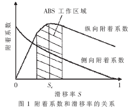
The working principle of the anti-lock brake system is to control the slip ratio of the wheel near the optimal slip ratio sc to obtain a high longitudinal and lateral adhesion coefficient to reduce the braking distance and ensure the braking of the car. Directional stability.
1 ABS hardware design
1.1 MC9S12DP256B MCU [2]
The MC9S12DP256B is a member of the Motorola 16-bit microcontroller HCS12 family, and its processing unit uses a 16-bit STAR12 CPU. On-chip resources include 256KB of Flash ROM, 12KB of RAM, 4KB of EEPROM, an 8-channel Pulse Width Modulation Module (PWM), an 8-channel Enhanced Capture Timer Module (ECT), and two 8-channel A/ D conversion module (ATD), two serial communication interfaces (SCI), three serial device interfaces (SPI), etc. In the Codewarrior integrated development environment, the program can be edited, compiled, downloaded and debugged online, making it easy to develop.
The ECT module has eight input capture/output compare (IC/OC) channels, four 8-bit or two 16-bit pulse accumulator (PAI) channels. When the module is running, the 16-bit free timer loops between $0000 and $FFFF at the set clock frequency. If a channel is set to I/O function, when the set edge of the signal under test comes, the input capture logic immediately captures the contents of the free timer into the 16-bit IC/OC register with a resolution of up to 1μs or more. High, and set the interrupt request flag, and then the program performs interrupt processing. If a channel is set to the OC function, the output compare logic automatically compares the contents of the IC/OC register with the contents of the free timer. Once the match, the corresponding pin is immediately operated, and the corresponding interrupt flag is set, and then the program performs interrupt processing. The time resolution of the pin output waveform can also be as high as 1μs or higher. The pulse counter counts only the number of inputs or edges and does not generate an interrupt. This function is used in the wheel speed acquisition algorithm.
The IC/OC shares eight pins with the general purpose I/O port PORTT. The four 8-bit PAI channels 0 to 3 share the pins PORTT0~3 with the first four IC channels IC0~3. In this controller, PORTT0~3 uses the pulse accumulator function to record the number of pulses of the four wheel speed sensors. When a real-time interrupt (RTI) is generated, the interrupt program reads the value of the pulse accumulator, calculates the speed of the wheel, and simultaneously clears the pulse accumulator to restart counting. PORTT4~7 uses the output compare function. When the value of the IC/OC register is equal to the value of the free counter, an interrupt is generated. The four interrupt programs process the ABS control strategies of the respective wheels.
1.2 Electronic Control Unit ECU Hardware Structure
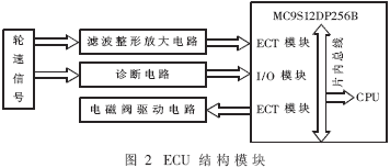
The core component of ABS is the Electronic Control Unit (ECU). The ECU circuit mainly includes four modules: power module, wheel speed signal processing module, arithmetic module, and solenoid valve drive circuit. Its basic function is to realize wheel speed acquisition, ABS fault detection, and control signal to solenoid valve according to control law. . Its structural block diagram is shown in Figure 2.
2 ABS control algorithm
The ABS control algorithm uses logic threshold control. The basic principle is that the acceleration and deceleration of the wheel is used as the main control threshold, and the slip rate of the wheel is used as the auxiliary control threshold. When the deceleration reaches the lower threshold, the decompression control signal is issued, and the acceleration reaches the first upper threshold. The boost control signal is issued. This cycle is repeated until the wheel speed drops to a lower value, exiting the ABS control.
Different road surface adhesion factors use different control strategies, so the first step in the algorithm is to identify the road surface. The method of road surface recognition is as follows: firstly, a pressure maintaining signal is issued to the wheel, and after a certain period of pressure, the road surface is identified according to the wheel reduction speed at this time. If the deceleration rate at this time exceeds the second upper threshold, it indicates that the road is highly attached; if the deceleration is between the first upper threshold and the second upper threshold, it indicates that the road surface is generally attached; if the wheel is reduced If the speed is less than the first upper threshold, it means that the road is low. The result of this is that the holding time of each wheel occupies most of the cycle time. If the cycle sequence of four wheels is used, it takes a long time to meet the timeliness requirement. However, if a multi-tasking real-time operating system is introduced, the algorithm is too complicated. Therefore, a method of introducing four interrupt processing is proposed, that is, each wheel has an independent timing clock, and the ABS control is executed in accordance with the respective set interruption time, realizing parallel control of four wheels. The interrupt time is set to ensure that the ABS control loop is executed ten to dozens of times in one second.
2.1 ABS detailed control strategy
Step 1: When the deceleration speed reaches the lower threshold, the system starts to maintain pressure and calculates the slip ratio until it is judged that the wheel enters the unstable area. Set the stage flag to Flag=2 and decompress.
Step 2: Determine the deceleration until the deceleration is less than the lower threshold, set Flag=3, hold pressure.
Step 3: Hold pressure for a certain period of time and judge the magnitude of the acceleration at this time: (1) If the acceleration is less than the first upper threshold, it is judged to be low adhesion to the road surface, set Flag=41, decompress. (2) If the acceleration is between the first upper threshold and the second upper threshold, it is judged to be a general road surface, and the flag is set to 42 and the pressure is maintained. (3) If the acceleration is greater than the second upper threshold, it is judged to be a high adhesion road surface, set Flag=43, and boost.
Step 4: Perform different control schemes according to the Flag value obtained by Step3.
Step 5: After one phase is completed, set Flag=1 to prepare to enter the next cycle.
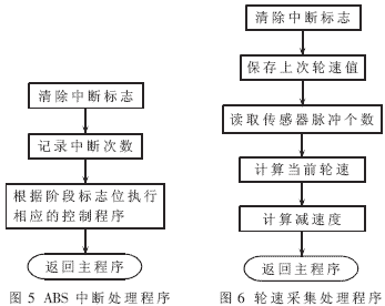
Each time the program enters the interrupt, it will perform different control phases according to the value of the phase flag until the entire ABS control is completed.
2.2 Wheel speed processing algorithm [4]
Wheel speed is the basis for calculating wheel acceleration and deceleration in the ABS program. The treatment of the wheel speed must satisfy: (1) good real-time performance. ABS's anti-lock control requires multiple cycles in a second, so the timeliness of wheel speed processing is very high, and the wheel speed processing program is not too complicated. (2) High precision. The accuracy of the ABS wheel speed has a great influence on the accuracy of the subsequent wheel acceleration and deceleration and the reference vehicle speed.
The method of wheel speed acquisition usually has a periodic method and a pulse counting method, and a pulse counting method is used here. The pulse counting method calculates the wheel speed by using the number of ring gears collected by the wheel speed sensor for a certain period of time, that is, the number of pulses. Its calculation formula is:
ω=2(πr/N)×(n/Δt) (2)
Where ω is the wheel angular velocity; r is the wheel radius; N is the number of ring gear teeth; n is the number of recorded pulses; Δt is the measurement time interval. It can be seen from equation (2) that the calculation error is mainly caused by the latter half. The timing of the MCU is very accurate, so the error of Δt can be neglected, but the number of pulses n is easy to cause the measurement error of ±1 tooth. The error generation diagram is shown in Figure 3.
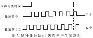
At low speeds, this ±1 tooth error is likely to cause ABS malfunction. If the measurement time interval Δt is increased, the ABS control aging is deteriorated. Here, the average method is used, that is, the Δt is kept constant, and the average of the pulse count values ​​of the last four times is calculated for each round of the wheel speed, thereby reducing the random error, which can reflect the change trend of the wheel deceleration, and It can prevent ±1 tooth error from causing large interference to the calculation.
2.3 Program flow
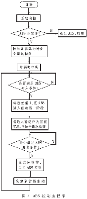
The program flow chart is shown in Figure 4, Figure 5, and Figure 6, respectively.
3 simulation platform and results
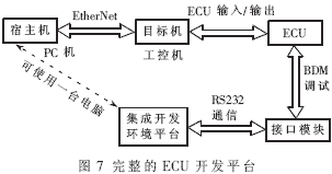
The simulation mode uses the xPC Target structure. xPC Target is a complementary product of the RTW (Real-Time Workshop) framework released by MathWorks, which converts Intel 80x86/Pentium computers or PC compatible machines into a real-time system and supports many types of I/O interface boards. The "dual-machine" solution of the host and target machines uses two PCs, where the host is used to run Simulink and the target machine is used to execute real-time code. The target machine runs a highly compact real-time operating kernel that communicates between the host and the target via an Ethernet connection. After the simulation is completed, the result data can be uploaded to the host for analysis and processing.
The whole vehicle model of the bus is built in the Matlab/Simulink environment of the host machine, and then the model is automatically converted into C code by using the xPC tool, and downloaded into the industrial computer through the Ethernet as the controlled object to realize real-time simulation. Signal reception and conversion in the hardware section was done using Advantech's data acquisition card PCL-726. The controller's development platform uses Metrowerks' Codewarrior 3.1, which is compiled and downloaded to the controller (ECU) and debugged in BDM mode. The semi-physical simulation platform is shown in Figure 7.
The simulation results of one of the wheels are shown in Figure 8.
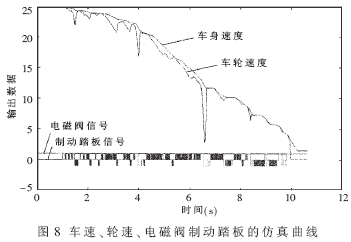
Fig. 8 is a single-round result diagram of the vehicle initial velocity of 25 mps and the road surface adhesion coefficient of 0.6. The four curves in the figure represent body speed, wheel speed, solenoid signal and brake pedal signal. The solenoid valve high state indicates boost pressure, the 0 state indicates holding pressure, and the low state indicates pressure reduction. After 1 second, the brake signal is given and the ABS starts to function. It can be seen from the figure that the burr is large in the place where the wheel speed is suddenly reduced, and the solenoid valve is in the stage of decompression or subsistence pulse; in the place where the wheel speed changes relatively gently, it is in the stage of supercharging or increasing the pulse. After 9 seconds, the body speed dropped below 3mps, automatically exiting the ABS control and returning to the normal brake. There was no wheel lock in the entire braking phase, and the result was ideal.
This paper introduces the design of passenger car ABS controller by using Motorola MC9S12DP256B, and proposes the use of four-level interrupt to realize parallel task processing. The simulation platform uses the rapid prototyping technology, and uses the xPC Target tool that comes with Matlab to directly generate the executable C code from the Simulink model to form a closed-loop semi-physical simulation platform. After simulating various working conditions, the controller has achieved good control effects and can be further optimized by real vehicle testing to achieve the finished product.
Quick Turn PCB fabrication and assembly service - Fast Turnaround PCB Prototype
My Dear customer friend, if your work needs to be completed as quickly and efficiently as possible, then you should choose Jinghongyi PCB as your best choice, because we know that speed is an important component of modern business equation. Forever!. We have fast turnaround PCB features, including Quick Turn PCB Manufacturing and PCB Assembly services, which can meet your tight project deadlines. We have a quick response mechanism to ensure that you speed up your order throughout the process (from quotation to delivery). Like all our services, our fast turning process is done internally, all of which are under one roof without outsourcing. Jinghongyi PCB is proud to be able to provide all customers with fast turnaround PCB services, including full certification of defense products.
Quick Turn Circuit Board Solutions:
We are a professional Quickturn PCB manufacturer from China. Engineers, assemblers, and designers from around the world have counted on us for their quick turn PCBs. Companies of all sizes know that they can rely on our key mission PCB.
We have the industry's leading percentage of punctuality, which has effectively solved many pressing issues for customers.
With our manufacturing facilities, we can provide quick turn circuit board FAB service and quick turn PCB prototypes solutions for all types of industries, including Medical, Transportation, Industrial Applications, Consumer Products, Aerospace, and Military.
Every online PCB order includes a full engineering review before your circuit board manufacturing begins, eliminating delays and quality problems.
- Quick Turn Delivery Option
- 24 Hour quick turn PCB orders.
- Printed Circuit Board pricing is available for 1-20 day deliveries.
Quickturn Printed Circuit Board Fabrication:
We offer Quick turn PCB due date as follows:
- 2 layer quick turn PCB --1 day
- 4-6 layer quick turn PCB --2 days
- 8-10 layer quick turn PCB --3 days
- 12-16 layer quick turn PCB --4 days
- 16-20 layer quick turn PCB -- 5 days
- 22-30 layer quick turn PCB --6 days
Materials that we keep in stock are:
- FR4 (Tg – 135C, 145C, 170C)
- Rogers Ultralam 2000
- Rogers RO4350
- Rogers RO4003
- Polyimide
- Teflon
- Black FR4
- Getek Copper
- Clad Thermal Substrates
- Hybrid (Rogers and FR4)
- BT Epoxy
- Nelco 4013
If you don`t see the material above, please contact us because we most likely have it in stock, but not listed above, or can special order it for you.
Finishes we are able to provide our customers:
- HASL – Leaded Solder Tin/Nickel
- HASL – Lead Free Solder
- Electroless Soft Gold
- Wire Bondable Soft Gold
- Nickel Flash Gold
- Electroless Nickel
- Immersion Gold OSP
- Electrolytic Nickel /Hard Gold and Selective Gold
- Immersion Silver
- Immersion Tin
- Carbon Ink
- ENIG
PCB Order Quantities
We don't specify the quantity of PCB orders. You can be quick turn Prototype PCB . It doesn't matter if the quantity is only one piece. We also provide small and medium batches and large orders.
We not only have no requirement and limitation in quantity, but also provide low cost quick turn PCB manufacturing service and assembly service as before, no matter how much the order is.
Due to production capacity, labor costs, spare parts procurement costs and other factors, we do not recommend that your quick turn PCB be carried out elsewhere. Quick turn PCB China has unique advantages, such as low price, exquisite production technology and timely and fast delivery capacity.
Quick Turn Prototype PCB
JHYPCB prides itself as one of leading suppliers of fast turnaround PCB prototype and low-volume production in the world. Our turn time can be as short as 24 hours after your Gerber files being reviewed and approved by our engineers, greatly saving you time in your work.
Delivery cycles are critical in prototyping new PCB designs. For your business, testing your design faster than your competitors is a competitive advantage. Let's learn more about your products and goals so that we can better understand the more success you need.
You may choose other time schedules to fit your budget, if your work timeframe is not that tight. We offer 48-hours and 72-hours shipping too.
In addition to the rapid prototyping version, we also provide other types of quick turn Printed Circuit Boards production services, such as:
Benefits of Quick-turn PCB prototype
"Time is money" and "Time is life". Rapid introduction of new products to the market means seizing market opportunities earlier than competitors.
But the quality of the product is also one of the magic weapons to win the market, which requires that the product be tested at the fastest speed before it is formally put into the market, so as to be able to develop and improve new functions of the product.
The core of electronic products is the circuit board. Quick turn PCB prototype manufacturing is also a point that engineers and project teams must do.
Before choosing quick turn PCB prototype manufacturer, customers must made sure that the production process, production capacity and delivery timeliness of PCB prototype manufacturer. The main requirement of quick turn PCB prototype manufacturing is fast speed and fast delivery.
1. Make prototype PCB at the fastest speed. Moreover, PCB manufacturer also checks the manufacturability of PCB files, such as Gerber files, before starting manufacturing, which further verifies the feasibility of customer PCB design.
2. Quick turn PCB prototype manufacturing services generally have a rapid response mechanism to ensure that PCB can be produced under strict time constraints;
3. In addition to the production and manufacture of PCB prototype, it also involves quick turn PCB assembly services. Quick turn PCB assembly is also one of the conditions under which products can be put into production as soon as possible.
Quick Turn PCB Assembly
Based on fast PCB manufacturing and fast steering component procurement support, we can ensure PCB assembly production.Our PCB assembly delivery time is the shortest in the industry. For prototype PCB, our delivery time is 24/48 hours or 5/10 days. For small batch production orders, you can choose delivery time of 10, 15 or 20 days. For medium-volume orders, we offer 15, 20 or 25 days.
With state-of-the-art surface mounting and through-hole equipment, we can assemble PCBs, including SMT, through-hole and hybrid technologies. We also carried out BGA rework and X-ray testing. We can assemble single-sided or double-sided PCBs using surface mount packages.
Quick Turn PCB in China
There are many PCB manufacturers in China, especially in Shenzhen.
Jinghongyi PCB, located in Baoan, Shenzhen, specializes in providing customers with high quality quick turn PCB manufacturing services and fast and timely delivery services. If you have quick turn PCB manufacturing requirements, we are your good choice. Here, you can get what you need in terms of speed, efficiency, quality and price.
In the process of manufacturing quick turn PCB, we will adopt the most suitable and economical materials to save your cost according to your requirements.
Because of the particularity of quick turn PCB to delivery cycle, if the quality of products has problems, it will not only delay time, but also cause unnecessary waste of production and increase cost.
If you demand quick turn PCB Board , just tell us your idea, we will make it!
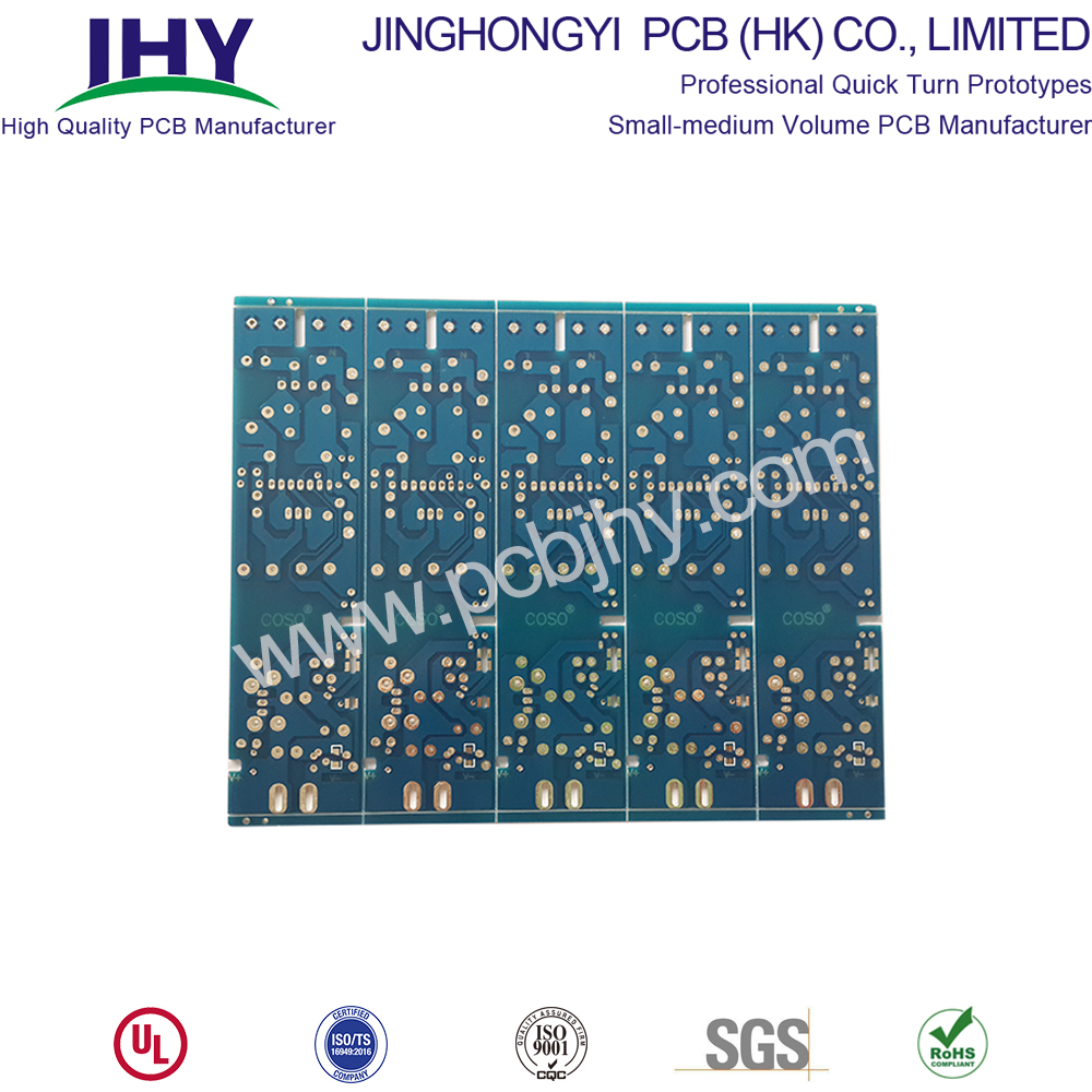
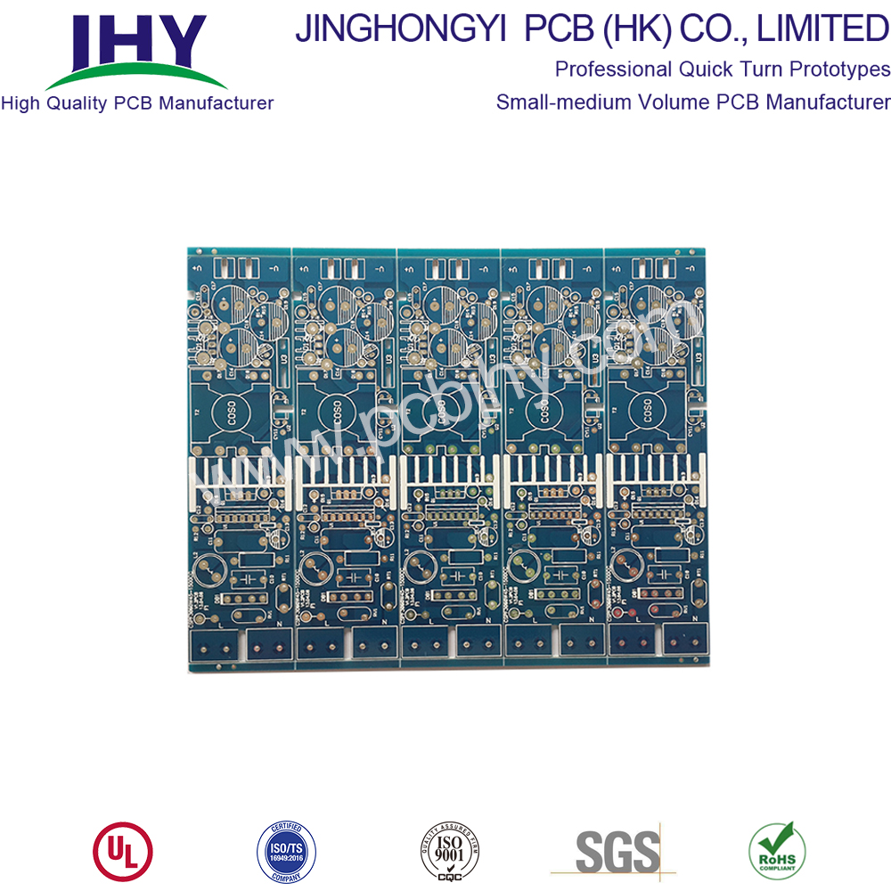
Quick Turn PCB
Quick Turn PCB,PCB Sample,Proto PCB,Fast PCB Prototype
JingHongYi PCB (HK) Co., Limited , https://www.pcbjhy.com
