Switching power supply transformer analysis, how to judge the quality of switching power supply transformer
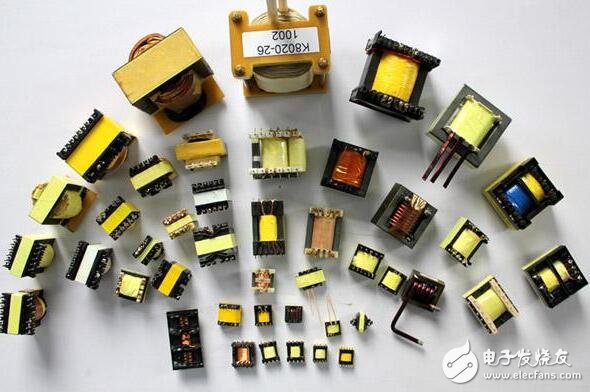
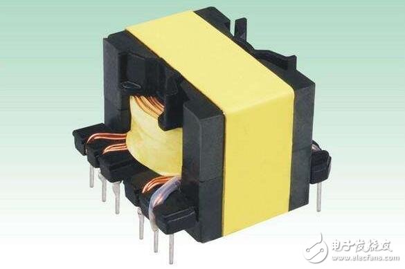
The switching power supply transformer is a power transformer with a switching tube. In addition to the voltage conversion function of the ordinary transformer, the circuit also has the functions of insulation isolation and power transmission, which are generally used in switching power supplies and the like involving high frequency circuits.

The switching power supply transformer and the switching tube together form a self-excited (or other) intermittent oscillator that modulates the input DC voltage into a high frequency pulse voltage. It plays the role of energy transfer and conversion. In the flyback circuit, when the switch is turned on, the transformer converts the electric energy into a magnetic field and can be stored, and is released when the switch is turned off. In a forward circuit, when the switch is turned on, the input voltage is directly supplied to the load and the energy is stored in the storage inductor. When the switch tube is turned off, the energy storage inductor performs a freewheeling flow to the load. Convert the input DC voltage to the various low voltages required.
The basic components of a switching power supply transformer:The main materials of the switching power transformer: magnetic materials, wire materials and insulation materials are the core of the switching transformer.
Magnetic material: The magnetic material used in the switching transformer is a soft ferrite. According to its composition and application frequency, it can be divided into two categories: MnZn and NiZn. The former has high magnetic permeability and high saturation magnetic induction, and has low loss in the intermediate frequency and low frequency range. The shape of the core is many, such as EI type, E type, EC type, etc.
Wire material - enameled wire: The enameled wire used for winding small electronic transformers is made of high-strength polyester enameled wire (QZ) and polyurethane enameled wire (QA). According to the thickness of the paint layer, it is divided into type 1 (thin paint type) and type 2 (thick paint type). The former's insulating coating is polyester lacquer, which has superior heat resistance, and the insulating electrical strength can reach 60kv/mm; the latter insulating layer is polyurethane lacquer, which has self-adhesiveness and self-welding performance (380 °C). Can be welded directly without going to the paint film
Pressure-sensitive adhesive tape: Insulating tape has high electric strength, easy to use and good mechanical properties. It is widely used in the layers of switching transformer coils, between groups and insulated. Must meet the following requirements: good adhesion, anti-stripping, with certain tensile strength, good insulation performance, good pressure resistance, flame retardant and high temperature resistance
Skeleton material: The switch transformer skeleton is different from the general transformer skeleton. In addition to being the insulation and supporting material of the coil, it also assumes the function of installation and fixing of the entire transformer. Therefore, in addition to meeting the insulation requirements, the material for making the skeleton should also have The tensile strength is equivalent, and in order to withstand the solder heat resistance of the lead, the heat distortion temperature of the skeleton material is required to be higher than 200 ° C, the material must be flame retardant, and the workability is good, and it is easy to process into various shapes.

The switching power supply transformer is divided into a single-excited switching power supply transformer and a double-excited switching power supply transformer. The working principle and structure of the two switching power supply transformers are not the same. The input voltage of a single-excitation switching power supply transformer is a unipolar pulse, which is also divided into a positive flyback voltage output; and the input voltage of the double-excited switching power supply transformer is a bipolar pulse, which is generally a bipolar pulse voltage output.
Characteristic parameters:
Voltage ratio: refers to the ratio of the primary voltage of the transformer to the secondary voltage.
DC resistance: that is, copper resistance.
Efficiency: output power / input power * 100 [%]
Insulation resistance: The insulation capability between the windings of the transformer and between the cores.
Electric strength: The degree to which the transformer can withstand the specified voltage within 1 or 1 minute.
The judgment of the switching power supply transformer is good or bad:Repairing the intermittent oscillation fault of the switching power supply circuit, after replacing all the suspect components except the switching transformer, it is often impossible to draw a more accurate conclusion about the quality of the switching transformer. In the case of suspicion, the maintenance has to be abandoned. . If you go through further inspections at this time, you can diagnose the quality of the switch transformer, that is, you can avoid the failure and make the repair complete.
Speaking of verifying the quality of the switch transformer, what induction method, ringing method / waveform method, etc., there is always a limited method, relying on comparison data, relying on the experience of the detector. If there is a simple and straightforward way, the test results are clear and plain, just fine. For example, the switch power supply sends a relatively safe low voltage, so that the circuit is in an unregulated open-loop state, and it will not pose any harm to the load circuit. You can safely power up the switching power supply, just fine. So how much volt DC voltage is added to the circuit as a safe voltage?
Coincidentally, there is a winding data of a switching transformer. The turns ratio of the DC500V winding to the 5V winding is about 20:1, the 5V winding is 5åŒ, and the 500V winding is 100åŒ. The oscillating chip uses 3844, and the maximum duty cycle of the output pulse is 50%. It can be roughly estimated. When the circuit is open loop, when the maximum duty cycle of the switch is output, the 500V winding allows the highest voltage input value of 200V. It can be seen that when the input voltage is not higher than DC200V, the switching power supply can ensure that the secondary load voltage is not higher than the rated value.
It can be seen that for this circuit, as long as the DC power supply of the original power supply of the DC530V power input terminal is less than 200V; for the 3844 directly to supply power higher than 16V (starting voltage), such as 18V, without changing the original voltage configuration, you can directly verify The switching transformer and other components in the switching power supply circuit are good or bad. In the open-loop working state, the voltage output of each winding of the switching transformer should be proportional to its turns ratio. If this condition is met, the switching transformer is good, if the output voltage of the secondary winding is significantly lower than this value. , indicating that the switching transformer is defective.
But this is not a general rule! Nearly repairing a Schneider ATV31 45kW inverter switching power supply, in the open loop state, after the input power supply voltage reaches DC50V or more, the output voltage of each channel has reached the rated value!
It can be seen that the switching transformer of each inverter has to be unequivocally sent to a higher supply voltage due to the uncertainty and non-uniformity of designing the number of side turns. It is best to have DC0~200V (100V) with adjustable stepless or variable gear. The power supply is sent from the low voltage first, and the output voltage is monitored at the same time, so that it is lower than the rated output voltage, which is convenient for monitoring. This maintenance process often surprises people: while verifying that the switch transformer is good or bad, the faulty components are also synchronized.

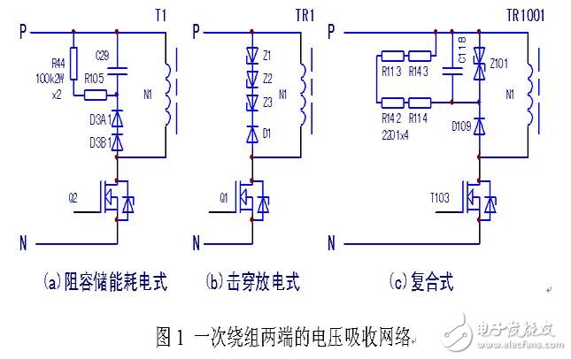
Looking at the picture first, the figure above shows the voltage absorption network connected in parallel across the primary winding N1 of the switching transformer. (a), (b), and (c) are common three-way circuit modes (such as composite, etc., which are my temporary names, which may not be accurate). The purpose is to provide the reverse current path of the switch. The amplitude of the reverse voltage between the drain/source (or collector/emitter) pole during the off period of the switch is suppressed, the safety of the switch tube is protected, and the accumulation of magnetic potential is avoided. When (a) C29 leakage in the circuit; (b) Z1~Z3 breakdown or leakage in the circuit; (c) Z101 breakdown or leakage in the C circuit, causing the switching transformer to overload, its secondary winding induced voltage reduce. At this time, for the switching transistor Q1/T103, although it will not cause its overload (being in the off period), the induced voltage of the secondary winding is reduced (see the circuit of Fig. 2), when the induced voltage of the N2 winding is low. (If the undervoltage operating threshold is lower than 10V/PC1), the internal oscillating circuit stops working, and the intermittent oscillating fault (expressed as melting) occurs. Note that this voltage intermittent oscillation phenomenon is caused by the undervoltage action of PC1, instead of the conventional overload protection caused by the overload of the secondary load circuit. At this time, the load circuit is checked, and of course there is no overload fault.

Let's take a closer look. When the C29 of the circuit in (a) of Figure 1 has been damaged by leakage, its leakage resistance is several thousand ohms; when the circuit of Z1~Z3 of (b) in Figure 1 breaks down or leaks, but The breakdown voltage is more than a few volts (beyond the range of the digital multimeter diode block, or the breakdown voltage is above 9V, beyond the voltage of the internal battery of the pointer multimeter) or its leakage resistance is also several thousand ohms; (c) in Figure 1 When the bidirectional breakdown diode Z101 of the circuit breaks down or leaks, whether it is a pointer multimeter or a digital multimeter, even if we have measured it patiently and carefully, it may not be able to draw accurate conclusions that C29, Z1, and Z101 are bad!
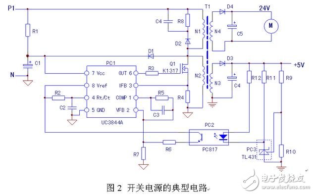
For convenience, take the circuit connected in parallel with N1 in Figure 2 as an example. When the leakage resistance of C4 is several thousand ohms, if using the diode block of the digital multimeter to measure (put the test leads on both ends of C4), reverse If the measurement is made twice, it is obvious that one of the measurement results is the forward voltage drop of D2, and one measurement shows infinity "1", and it is impossible to obtain an accurate measurement result of C4 leakage; if the electric resistance of the pointer type multimeter is not measured If the measured value is the C4 leakage resistance and the total parallel resistance of the R8 and the associated parallel external circuit, the value is large, and it is not easy for people to judge that C4 has been damaged by leakage.
Like the circuit (b) in Figure 1, when Z1 is damaged, but its breakdown value is much higher than the battery voltage in the multimeter, only the forward resistance value (or forward voltage drop) of the diode is measured. The reverse resistance value is also extremely large; the circuit of (c) of Figure 1 has positive, reverse conduction voltage drop or positive and negative resistance values ​​if its breakdown breakdown value is much higher than the internal resistance voltage of the multimeter. It is great, it is impossible to judge that it has broken!
It should be known that the leakage current of the capacitor or the breakdown state of the diode will only be manifested when the voltage applied across the component is above a certain threshold. When the multimeter is tested under low voltage conditions, the faulty component sometimes "behaves normally." This is why the electrician is trying to separate the multimeter from the insulation shaker when testing the insulation between the cable or the winding.
In summary, when the components such as C29, Z1, Z101 in the figure are damaged, in fact, we have measured the component many times, and still be blinded by the measurement results, and the measurement judgments of other components are also very obvious (no When the problem occurs, there will be a fault judgment in the mind, maybe the switch transformer is broken (internal turn-to-turn short circuit), right? Some repairers may take further measures, such as replacing the 3844 and all peripheral circuits with the oscillating small board (the voltage absorbing circuit connected in parallel with the N1 windings is not moving). After the replacement, the result is still the fault, so it seems more The fault of the switching transformer was confirmed. If the switch transformer of the same model can be replaced by the test, the faulty machine that should be easily repaired may have slept in a corner from now on.
It can be imagined that the probability of the switch transformer being broken is extremely low. For the "difficult fault" exhibited by the intermittent oscillation, it will be misjudged as the damage of the switch transformer, which indicates that there are limitations in our fault detection method.
Let's look at two examples of fault detection:
1. After the switching power supply is powered on, a beep sounds, and the output DC voltage of each channel is extremely low and unstable. Check from the load circuit first, no damage to the components. Later, the voltage absorption network in parallel with the N1 winding was mainly detected, and there was no abnormality. Take the oscillating small board, replace the oscillating chip and peripheral circuits, and the fault remains after power-on. There is no problem in the description, oscillation, and voltage regulation. There is no abnormality in rechecking the load circuit. Overhaul is in trouble.
Think of whether the switch transformer is broken? You must first rule out this possibility.
Directly connect DC18V to pins 7 and 5 of 3844. Connect DC100V to the DC530V power input terminal of the switching power supply. After power-on, the circuit starts to work. After a while, Z101 in the circuit of Figure (c) starts to smoke. Observe that this circuit is a compound voltage absorbing circuit. There is a RC absorption circuit connected in parallel with Z101. After temporarily removing Z101, measure the DC output voltage of each channel, and its height is proportional to the input voltage. It has been self-evident).
At this point, the cause of the failure is very clear. Three series of 100V voltage regulators are used in series to replace Z101. After power-on test, the switching power supply works back to normal.
2, the failure phenomenon is the same as above, the inspection method is the same as above. After power-on, Z1 and Z2 overheat and smoke. At this time, the quality of the switching transformer is self-evident, and the "culprit" of intermittent oscillation failure has been hidden. Replace the Z1 and Z2 with two 120V voltage regulators. After the power is turned on, the switching power supply works back to normal.
Let me explain it later. Then why use the original power supply DC530V, the circuit is in intermittent oscillation, and the circuit is connected to DC18V and DC100V respectively, which can quickly make the faulty components have nowhere to hide? See Figure 2 circuit.
1. The power supply of the PC1 oscillator chip is taken from the N2 winding. When the C4 is seriously leaky, the storage energy of the switch transformer is insufficient, the induced voltage of N2 is lowered, the internal undervoltage detection circuit of PC1 operates, and the circuit is in intermittent oscillation state.
After independently feeding the DC18V power to the PC1, the PC2 can work stably and expose the faulty components.
2. In the DC530V power supply terminal of the switching power supply, send DC100V. This is a fuse voltage. Under the condition that the voltage is out of control due to the fault, the DC output voltage of each channel will not exceed the rated value and damage the load circuit. You can safely detect the working status of each part of the circuit, thus exposing the root cause of the fault. If the 0~200V adjustable DC power supply is better at hand, while monitoring the output voltage, slowly increase the input power supply voltage, and further detect the process of the circuit from the open loop to the voltage regulation control, verify whether the voltage regulation of the circuit is normal.
Whether the game can be played smoothly depends on the low latency of the projector, whether it can be optimized to within 30ms, or within 50ms, which is difficult for non-professionals to perceive. However, the cable and network speed and the configuration of the computer (game console) have an impact on the game delay, so you can't completely throw the pot to the display device.
The first is the problem of memory. Be sure to choose a larger one, the bigger the better, otherwise the screen will freeze. The second is that the resolution must be above 1080p, otherwise the details of the projected game screen will not be clear, which will greatly affect the game experience and viewing experience. The other is about motion compensation. The game screen is generally faster for animation playback. It must be equipped with motion compensation, otherwise the screen will be stuck.
gaming projector,gaming mini projector,gaming projector best buy,4k gaming projector hdmi 2.1,best gaming mini projector
Shenzhen Happybate Trading Co.,LTD , https://www.happybateprojector.com
