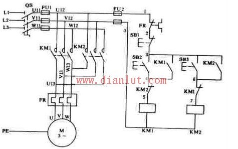
Master/reverse control circuit schematic of contactor interlock

The electrical and electronic schematic diagram of the forward and reverse control of the three-phase asynchronous motor contactor interlock is shown in the figure. Two contactors are used in the line, namely the contactor KM1 for forward rotation and the contactor KM2 for reverse rotation, which are respectively controlled by the forward rotation button SB2 and the reverse rotation button SB3. The phase sequence of the power supply connected to the main contacts of the two contactors is different. KM1 is wired in the L1-L2-L3 phase sequence, and KM2 is reversed in the phase sequence of the two phases. There are two control circuits, one forward control circuit composed of buttons SB2 and KM1 coils, and the other reverse control circuit composed of buttons SB3 and KM2 coils.
Control principle: When the forward rotation start button SB2 is pressed, the power supply phase passes through the dynamic disconnection contact of the thermal relay FR, the dynamic disconnection contact of the stop button SB1, the movable joint contact of the forward rotation start button SB2, and the reverse AC contactor KM2. The closed auxiliary contact and the forward-rotating AC contactor coil KM1 act to electrify the forward-rotating contactor KM1, and the main contact is closed to cause the motor to rotate in the forward direction and self-maintaining operation through the normally open auxiliary contact of the contactor KM1. The reverse start process is similar to the above, except that after the contactor KM2 is activated, the two power lines U and W phases are changed (ie, the power phase sequence is changed), thereby achieving the purpose of reversal.
Interlocking principle: The main contacts of the contactors KM1 and KM2 must not be closed at the same time, otherwise the two-phase power supply short-circuit accident will occur. In order to ensure that one contactor is energized, the other contactor cannot be electrically operated to avoid the phase-to-phase short circuit of the power supply. In the forward rotation control circuit, the normally closed auxiliary contact of the reverse contactor KM2 is connected in series, and The normally closed auxiliary contact of the forward rotation contactor KM1 is connected in series in the inversion control circuit. When the contactor KM1 is energized, the normally closed contact of the KM1 in the reverse control circuit is disconnected, and the reverse control circuit is cut off to ensure that the main contact of the KM2 cannot be closed when the KM1 main contact is closed. Similarly, when the contactor KM2 is energized, the normally closed contact of the KM2 is disconnected, the forward rotation control circuit is cut off, and the occurrence of a short-circuit accident of the two-phase power supply is reliably avoided. When a contactor is energized, the function of making the other contactor unable to perform electric action by its normally closed auxiliary contact is called interlocking (or interlocking). The normally closed contact that implements the interlocking function is called an interlocking contact (or an interlocking contact).
Enershare's commitment to future-ready energy solutions for smart home innovations, Enershare`s Energy Storage Systems create a flexible energy maintenance system for homeowners who want to take more control of their home energy use, it is intended to be used for home battery energy storage and stores electricity for solar self-consumption, load shifting, backup power, and off-the-grid use. you can use it anytime you want-at night or during an outage.
Lithium Battery Storage,Lithium Energy Storage,Off Grid Solar Power,Lithium Energy Storage System.
Rack-mounted,Lithium Battery Storage,Lithium Energy Storage,Off Grid Solar Power,Lithium Energy Storage System
Shenzhen Enershare Technology Co.,Ltd , https://www.enersharepower.com
