How to use LED circuit to illuminate led?
I have introduced a lot of conceptual knowledge and done a lot of preparation work. From this section, we officially started learning MCU. We will use a microcontroller to do a very simple job: illuminate a light-emitting diode (LED: Light-Emitting Diode).
LED introductionLet me briefly introduce the LED. LED is a kind of semiconductor device. In fact, everyone is not strange to LED. The indicator lights of various electrical appliances, keyboard lights of mobile phones, backlights of LED liquid crystal screens, high-brightness LED flashlights, etc. are all illuminated by LEDs. LEDs have two main uses, one as an indicator light and the other as illumination. The LEDs used for lighting are generally high-power LEDs, which require a large voltage and current to work properly. And what we are going to use here is the low-power LED used as the indicator light. A common low-power LED, with its positive and negative voltages plus a voltage of about 3V, will illuminate. When it is normally illuminated, the current is about 2~5mA. It should be noted here that the LED has the positive and negative poles, and the reverse will not emit light. In addition, the voltage should not be too high, which would burn out the LED. For a more detailed introduction to LED, you can refer to books such as electronic components.
Circuit designAs described above, the IO port of the MCU can output high and low levels, and the LED is realized by the output level of the IO port. If we connect the positive pole of the LED to the positive pole of the power supply, the negative pole is connected to an IO port of the microcontroller. Let the IO port of the MCU output a low level, that is, a voltage close to 0V. At this time, there is a voltage difference between the two ends of the LED, and it can emit light; if the IO port outputs a high level, the LED will be extinguished.
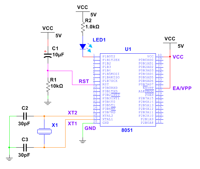
Since the 51 MCU we use is 5V power supply, and the LED needs 3V voltage, we need to connect a suitable resistor in series with the LED, otherwise it will burn out the device. We can choose any one of 32 IO ports of P0~P3, here is P1.0. The circuit diagram is as follows, the value of the resistor is recommended to be between 330Ω ~ 1kΩ.
By the way, the calculation process of the resistance value is attached:
1. The resistor and the LED are connected in series. When the LED is lit, the total voltage is 5V, and the LED needs 3V, so the voltage on the resistor is 5-3=2V.
2. The current of the LED is 2~5mA. If it is calculated as 2mA, the voltage on the resistor is 2V and the current is 2mA. According to Ohm's law, the resistance should be 2V/2mA=1kΩ.
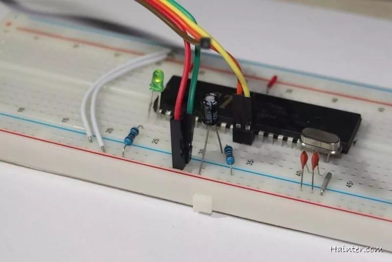
 Breadboard building circuit
 The circuit we built on our own breadboard is as follows. I connect the LED to the P1.0 port (the circuit for soldering the universal board is not provided here, you can build it yourself):
If you are using a development board with an LED module on it, you can view the circuit diagram. For example, my development board circuit diagram:
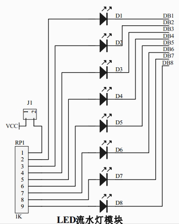
In the figure, VCC is connected to RP1 through J1, and RP1 is the exclusion resistor. Pin 1 in the figure is a common pin. There is a 1k resistor between each pin of pin 2 to pin 9~9 inside the resistor. A total of eight 1k resistors are arranged, so it is called exclusion. J1 is equivalent to a switch, which is actually a socket composed of two pins. If the jumper cap is plugged in, it can be turned on; if the jumper cap is removed, it will be disconnected. The advantage of this design is that if I want to use the LED module to plug in the jumper cap; and if I don't use the LED module, but the IO port is used for other purposes, then the LED will not interfere with my circuit, because the LED One end is connected to the IO port, the other end is connected to the resistor, and the other end of the resistor is suspended, and there is no access circuit.
In the figure, the labels DB1~DB8 are connected to the IO port of P1.0~P1.7 in the minimum system circuit of the MCU, so in the case of J1 conduction, the high and low levels of P1.0~P1.7 can Control the LEDs D1~D8 are on and off.
Specific operationFor microcontroller programming, we usually use Keil software. Keil software can be downloaded from the Internet. The installation process is not described here in detail. There is basic computer operation knowledge and it should be installed without problems. It is worth noting that when installing, try to install it in the English directory. It is best not to use Chinese to avoid problems with the program.
We opened the Keil software and prepared to write the program to the microcontroller. You can follow the steps below (here, the Keil uv4 English version is used as an example. If you are using other versions of Keil, the operation is basically the same).
First, build and configure the project1. First create a new project: Click on Project – New uVision Project in the menu.

2, then we create a new folder for our project on the computer, here I use Project01 – LED, you can name it yourself, but it is best to have an English name.

3. Open the folder, enter the name of the project, and click Save. Here I am entering the LED.
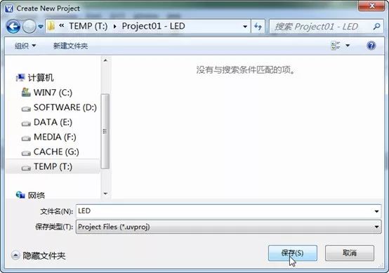
4, then pop up a window, let us choose the model of the microcontroller. We use the STC89C52RC, and there may not be an STC microcontroller. We only need to select the Atmel series AT89C52 microcontroller that is fully compatible with STC. Click OK to confirm.
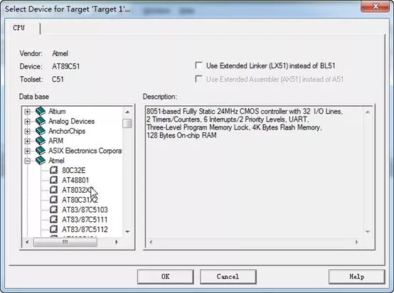
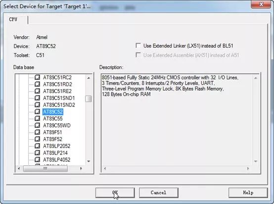
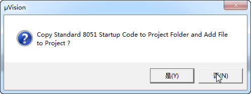
5, then a window will pop up, prompting us whether we need to add the 8051 startup code to the project, click No (if we need to use the custom startup code, you can click Yes, then modify the startup code. And we use programming The C language, in general, does not need to modify the startup code. As for the usefulness of the startup code, we can wait until we know more about the microcontroller to find relevant information to learn).
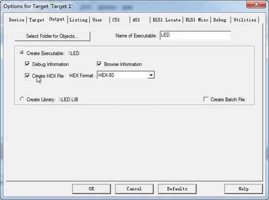
6, below we make a simple setup of the project. Right-click on Target 1 and select the first option for Target 'Target1'... to bring up the project property settings window.
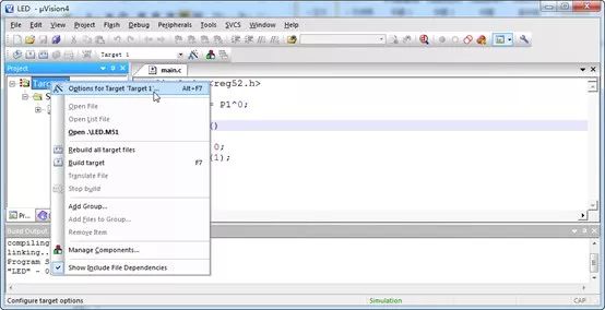
7. We open the Output tab and check Create HEX File, then click OK to confirm.
 Second, create a new source file and add it to the project
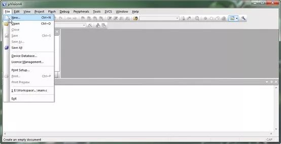
 1. The project is newly built and configured. Below we start to create a new program source file. Click File-New in the menu and a new file appears, as shown.
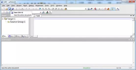
2. Then we click the Save button and save it to the project folder Project01 – LED and save it as a file with the extension “.câ€, such as main.c. The important thing to note here is that the source file is actually just a plain text file, but the extension is c instead of txt. We just created a new main.c file, or you can create a new text document in Explorer and rename it to main.c.
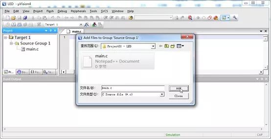
3. The source file is new. The source file is just a separate text file, and the project file is now completely independent and unrelated to the newly created source file. We're going to add the newly created main.c file to our project: right click on Target 1/Source Group 1 and select Add Files to Group 'Source Group 1'... from the menu to add the file.

4. Double-click the file main.c you want to add, or select it and click the Add button. You can see from the Project window on the left that the file has been added to the project. The pop-up window is not closed at this time, because it is convenient to continue adding other files. Since we only need to add one file and add it now, click Close to close the pop-up window.
 Third, write the program and compile
 1. We open main.c and start writing the program. The program we wrote is as follows and saved. As for what this program means, it will be described in detail later. Note that the LED set in the program I gave is P1.0. If the IO port of the LED in your development board or your own circuit is not P1.0, you need to modify the sbit line according to the format I gave. . This point also fully embodies that the MCU programming is closely related to the actual hardware circuit, and the program and circuit must be matched to operate normally.
#include
Sbit LED = P1^0;
Void main()
{
LED = 0;
While(1);
}
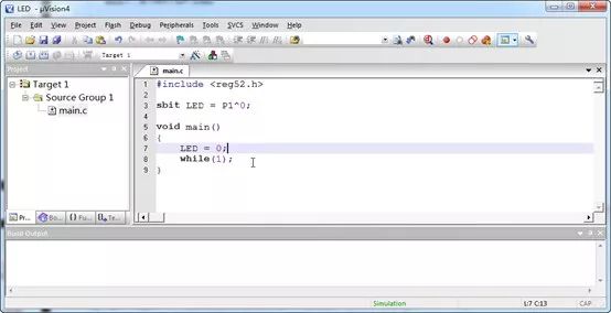
2. Click the double arrow button at the top left to compile all the files. We see that the output window below shows the compilation completed. “creating hex file from 'LED'†indicates that the HEX file was created when it was compiled (HEX file is a hex file) It will be written into the MCU. It is equivalent to the executable file ".exe" in Windows), "0 Error(s), 0 Warning(s)." indicates that the compilation is successful and the program has no syntax error. If you are prompted that your program is wrong, please check carefully and see if there is any missing semicolon.
 Fourth, programming the program into the microcontroller
 Under the project folder, we can see the generated LED.hex file, which is exactly what we need. Below we will burn the LED.hex file into the microcontroller. I have already introduced the knowledge of downloading the MCU program. Here we will introduce the general steps of downloading the program. Since the computers and development boards used by everyone are not exactly the same, it may fail to download. I hope that readers who have not succeeded in downloading should not be discouraged. If you want to deal with the download failure, please continue to see the following content. The steps to download the program are as follows:
1, set the microcontroller model, here we set the microcontroller to STC89C52RC.
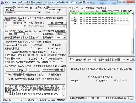
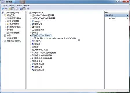
2. Set the serial port number, baud rate and other parameters. Since we generally use USB to serial port chip, it is not a real RS232 serial port, so the serial port number is not fixed. When plugging in the adapter board or MCU learning board, we should open the device manager as shown in the figure (XP system: right click "My Computer" → "Properties" → "Hardware" → "Device Manager"; Win7 System: Right click on "Computer" → "Management" → "Device Manager"). Find the Port (COM and LPT) option, expand it, and there will be an item like "Prolific USB-to-Serial Comm Port (COM1)" or "USB-SERIAL CH431 (COM1)". The COMx in parentheses is the port number we are looking for. Fill in the STC-ISP (if there is more than one, you can plug in the MCU learning board to see which item will be refreshed). If unfortunately, your serial port number is large and exceeds the range that STC-ISP can set. You can right click on the item displayed in the device manager to change the COM port number. Options such as baud rate are generally set by default and do not need to be set.
3. Click “Open Program File†to select the HEX or BIN file to be programmed. The HEX or BIN file is the compiled machine code. After opening, you can see the corresponding hexadecimal number in the program file on the right side of the STC-ISP. You can choose the machine code generated by the program you wrote yourself, or you can find some test programs in the STC-ISP test-hex directory. Here we select the HEX file that was just compiled.
4. Click “Download†first, then turn on the power switch to power on the microcontroller. STC-ISP will display the program being programmed later. If you forget to turn off the power before clicking “Downloadâ€, or the program can't download, you don't need to click the “Stop†button, you can power off and then try it. It usually takes a few seconds to download and the download is successful in STC-ISP.
5. Observe the results of the program execution and debug the program if necessary.After the general program download is completed, if the P1.0 port is connected with an LED, the circuit connection is correct, and the LED will magically light up. We have succeeded in letting the microcontroller execute our own program. Everyone who starts a single-chip computer often gets excited when he sees this scene, just as I am happy to learn MCU for the first time. Since the program here is very simple, basically no debugging is required. At this point you can show off to your friends and show the fruits of your labor.
Patent Vape,E-Cigarette Vape Pens,E-Cigarette Vaporizer Pen,Disposable Vape Puff Bar
Guangzhou Yunge Tianhong Electronic Technology Co., Ltd , https://www.e-cigarettesfactory.com
