How to use AD8283 to design automotive radar analog front-end circuit?
In the United States, the traffic accident mortality rate has been declining in recent years. In 2010, it was 3% lower than in 2009, reaching a new low since 1949. The reduction in fatalities from accidents is attributed to the analysis of the U.S. Department of Transportation, which is due to the widespread application of automotive safety technologies, especially the active safety technologies that have gradually emerged in recent years, such as automotive front-end anti-collision warning systems, lane change assist systems, etc. It is also the development direction of today's automobile safety.
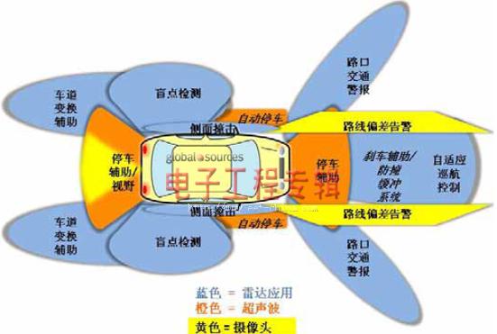
In the above-mentioned active safety applications, radar technology has become a key element. In recent years, automotive radar technology has continued to be a hot electronic technology that the technical media pays attention to. Although the application of this technology in automobiles can be traced back at least more than ten years ago, until today, radar technology is no matter in terms of application breadth or application depth. , Is still very limited, is still a "patent" of some mid-to-high-end cars, and more of it stays in parking assistance applications. In fact, radar technology has great potential in automotive safety applications: including lane change assist, side collision avoidance detection, adaptive cruise control, driver blind spot detection, brake assist/anti-collision buffer system, intersection traffic warning, and so on.

Figure 1: Radar technology is widely used in automotive active safety
An analog front-end circuit that completely changes radar design
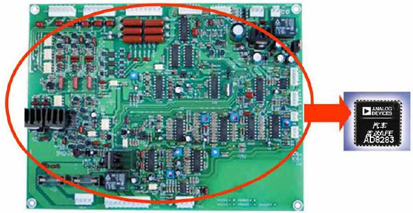
However, most of the current automotive radar systems are relatively low-integrated, occupy a large space, and are expensive, which limits the radar technology that can bring important safety guarantees for more passengers and passengers to high-end cars. The AD8283 launched by ADI integrates the analog front end (AFE) of the automotive radar receiver into a small chip, which greatly improves the integration and reduces the size and cost of the automotive radar. The low-cost, high-performance AD8283 is expected to apply radar active safety technology to more low-end and mid-range cars.

Figure 2: AD8283 greatly reduces the traditional radar analog front-end circuit
For radar system designers and OEM manufacturers, AD8283 has three major advantages. The first is size. It realizes the integration of many discrete components in a 10mmx10mm package. This is very important, because the radar sensor module must be suitable for installation in a small area in the car, such as behind the shock absorber. These areas are not designed to accommodate this. Designed for similar electronic devices; the second is ease of use. AD8283 provides users with user-programmable and flexible settings (programmable functions will be described in detail below) so that users can improve performance under different working conditions and make the system easier Develop and accelerate the launch of new systems; the third is cost. The price of this product is lower than that of discrete devices. Compared with discrete device solutions, the cost can be reduced by more than 50%. Therefore, OEM manufacturers will be able to provide more on more models. The application provides a radar system, which will give more drivers a safer driving experience.
The six-channel AD8283 allows the radar system to receive a larger number of transmitted signals and decode them for target recognition and classification. This makes the positioning time more abundant, thereby improving the radar's ability to resolve the approximate size of the target. The new analog front-end chip also has the advantage of low power consumption. The power consumption per channel is only 170mW. This new device has passed AEC-Q100 certification and can work stably in the automotive application temperature range of -40°C to 105°C.
Signal link analysis
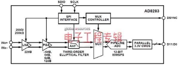
AD8283 integrates a low-noise amplifier (LNA), programmable gain amplifier (PGA), anti-aliasing filter (AAF), and ADC. For traditional discrete solutions, the circuit composed of all these components should satisfy the radar system The key performance index requirements of this chip are very challenging, but the advantages of the chip's single-chip integration have resolved these headaches that have always caused engineers. These performance indicators include LNA noise, PGA gain range, AAF cutoff characteristics, and ADC sampling rate and resolution. The following will analyze in detail the internal circuit structure of the AD8283 and how to achieve these performance requirements.

Figure 3: AD8283 internal signal link
The LNA is located at the front end of the signal path, so good noise performance depends on the ultra-low noise LNA, which can effectively reduce the noise input to the subsequent PGA and AAF circuits. In order to achieve a good input impedance matching, AD8283 provides an optional input impedance of 200Ω or 200kΩ, and the design engineer can make programming choices through the SPI port. The low-value feedback resistance and current drive capability of the output stage enable the LNA to obtain an output reference noise lower than 3.5nV/√Hz at a channel gain of 34dB. Due to the use of a fully differential topology and negative feedback, the second-order distortion is minimized. The differential signal achieves a smaller signal swing at each output terminal, further reducing the third-order distortion. In order to obtain the best noise performance, it is recommended to match the impedance of the positive and negative input terminals, so that common mode noise can be effectively suppressed.
The programmable amplifier integrated inside the AD8283 achieves great flexibility in applications. Design engineers can easily implement amplifier programming settings through the SPI interface: gain programming in the range of 16dB to 34dB in 6dB steps through the SPI port; at the maximum gain , The input-referred voltage noise is less than 3.5nV/rtHz. AD8283's flexible amplifier settings are very critical for automotive applications, because the solution can automatically adjust the characteristics of the radar sensor according to the distance, such as the need to prevent system overload and avoid return The amplitude of the signal will be very high and must be attenuated.
The anti-aliasing filter integrated inside the AD8283 realizes the band rejection filter before the signal enters the ADC, thereby avoiding signal aliasing. This filter combination uses pole and zero filtering to implement a third-order elliptic filter, so that signals outside the cut-off frequency can roll off quickly. The filter uses the on-chip fine-tuning function to correct the capacitance value to set the desired cut-off frequency. This fine-tuning method reduces the cut-off frequency variation caused by the standard IC process tolerances of resistors and capacitors. The cut-off frequency of the default -3dB low-pass filter of the chip itself is 1/3 or 1/4 of the ADC sampling clock frequency, which can be adjusted to 0.8, 0.9, 1, 1.1, 1.2 or 1.3 times the frequency through the SPI interface. Usually the fine-tuning function is turned off to avoid changing the capacitor settings at critical moments. This function can be turned on or off through the SPI interface. After the system is powered on and the filter cutoff frequency or ADC sampling rate is reprogrammed, the fine-tuning initialization of the filter must be completed. It is recommended that fine-tuning actions can be performed intermittently when the system is idle to compensate for temperature drift.
For all sensor applications, ADC technology is often critical. AD8283 utilizes ADI's industry-leading technology in this field and integrates a 12-bit, 80MSPS (million samples per second) ADC, which can fully meet the requirements of most automotive radars, with a signal-to-noise ratio (SNR) of 67dB and no spurious The dynamic range (SFDR) reaches 68dB. Under the condition of fully meeting the application requirements, only a single ADC circuit is integrated inside the AD8283, and a multiplexer circuit is integrated before the ADC, thus avoiding the use of an independent ADC for each channel. So as to effectively reduce the cost of the chip. After each ADC sampling is completed, the multiplexer automatically switches and scans between the active channels, and the on-hold time of each channel is one clock cycle. The switching is synchronized with the ADC sampling to ensure that the switching time and channel setup time will not be the same as the ADC sampling There is a conflict.
Design suggestions for automotive radar based on AD8283
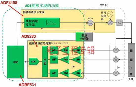
The main application of AD8283 is high-speed ramp frequency modulation continuous wave radar (HSR-FMCW), which is also a technology widely used in current automotive radars. Figure 3 is a simplified system block diagram of the FMCW radar. The automotive radar system based on AD8283 usually needs to use key circuits such as DSP and PLL. ADI provides key supporting devices for this.
The FMCW radar system requires very high radio frequency performance, and the current method that highly relies on the linearity of a voltage-controlled oscillator (VCO) is very complicated, lacks flexibility, and is costly, so there are many design challenges. ADI launched the industry-leading ADF4158 PLL device last year to provide a good choice. ADF4158 is a feature-rich 6.1GHz programmable device that can meet the needs of various FMCW radar system design engineers through simple configuration.
The FMCW radar system implemented using the ADF4158 has a highly linear ramp characteristic completely independent of the linearity of the VCO, which can improve the radar resolution, reduce the cost and the complexity related to system calibration. For those cost-sensitive designs, the cost advantage of ADF4158 is also attractive. The cost of ADF4158 based on reliable BiCMOS process technology is only one third of similar devices.
Similarly, for DSP matching options, design engineers can choose ADI's very mature and low-cost ADSP BF531. This processor has been widely used in the industry. ADI can provide low-cost matching development kits and a large number of application code libraries. Greatly reduce system design costs and speed up product launches. Therefore, the combination with the cost-effective AD8283 will be able to achieve a more cost-competitive automotive radar system, which will further help manufacturers to implement radar active safety technology in a wider range of low- and mid-range cars.

Figure 4: In addition to AD8283, ADI also provides PLL and DSP devices with both cost and performance advantages
As passive and active safety systems begin to merge with other electronic systems in automobiles, such as communications and advanced driver assistance, automobiles are becoming more and more autonomous and intelligent. With the application of radar detection technology, electronic systems that react much faster than the driver will be able to take over control and reduce the frequency and severity of accidents. In the field of advanced driver assistance systems, systems using radar technology are becoming more and more common. Adaptive cruise control, blind spot detection, and two-sided vehicle warning are all systems that have been put into use today, which can be used to remind or help driving Clerk controls the car. In some cases, these systems can even intervene and control the car to avoid dangerous situations.
As a leader in the fields of MEMS, RF, amplifiers, converters and DSP, ADI can provide leading technologies for the realization of such systems. The current challenge faced by manufacturers is how to make products with the smallest size, highest reliability, robustness under higher and lower temperature working conditions, and easy configuration at the lowest cost. ADI launched Industry-leading technologies such as AD8283 and ADF4158 help automakers overcome these challenges with low cost, smaller size and shorter development time.
Water Purifier Pressure Sensor
Shenzhen Ever-smart Sensor Technology Co., LTD , https://www.fluhandy.com
