Description of CC1020 Micropower Wireless Data Transmission Module Brief Talk on CC1020 Circuit Application
This article is mainly about the introduction of CC1020, and focuses on the CC1020 micro-power wireless data transmission module in detail.
CC1020cc1020 is an ideal UHF monolithic transceiver chip. It is mainly used in the ism (industrial, scientific research and medical) frequency band and the srd (short range device) in the 426/429/433/868/915mhz frequency band. It can also be used in the frequency range of 402mhz~470mhz and 804mhz~940mhz multi-channel equipment.
cc1020 module features
1. The frequency range is 402mhz-470mhz. 2. High sensitivity (up to -118dbm for 12.5khz channels) 3. Programmable output power, maximum 10dbm 4. Low current consumption (rx:19.9ma) 5. Low voltage power supply (2.3v) Up to 3.6v) 6. The data rate can reach up to 153.3kbaud. 7. The spi interface is equipped with internal registers. 8. The standard dip spacing interface is convenient for embedded applications. 9. The communication distance is long. The 10dbm power condition can transmit about 600 meters outdoors.
cc1020 working parameters
The main operating parameters of cc1020 can be programmed through the serial bus interface, such as output power, frequency and afc. In receiving mode, cc1020 can be regarded as a traditional superheterodyne receiver. The rf input signal is amplified by the low-noise amplifier (lna and lna2), and then flipped through the integrator (i and q) to produce an intermediate frequency if signal. In the intermediate frequency processing stage, the i/q signal is converted into a digital signal by adc after mixed filtering and amplification. Then perform automatic acquisition control, channel filtering, demodulation and binary synchronization processing, output digital demodulation data on the dio pin, and obtain synchronized digital clock data on the dclk pin. rssi is in digital form and can be read out through the channel interface. rssi can also be used as a programmable carrier detection indicator. In the transmission mode, the synthesized rf signal is directly fed to the power amplifier pa. The RF output is the fsk signal, which is generated by the digital bit stream fed to the dio pin through fsk modulation. A high frequency filter can be used to get Gaussian frequency shift keying gfsk. The receiving/sending switch circuit inside the chip makes the antenna easy to access and match.
cc1020 signal transceiver interface
The connection between the cc1020 signal transceiver interface and the microcontroller is shown in Figure 1. The microcontroller uses pins p2.6 and p3.4 to connect with the bidirectional synchronous data interface dio and dclk of the cc1020.
Figure 1 cc1020 and microcontroller connection circuit A bidirectional pin of the microcontroller is connected to the dio of the cc1020 for data transmission and reception (input and output). dclk provides data timing and must be connected to an input of the microcontroller. Data output can choose to use a separate pin. At this time, set the cc1020 interface register sep_di_do=1. In synchronous mode, the lock pin is used as data output, while the dclk pin is used as data output in asynchronous mode, and the dio pin is only used for data input. A pin of the microcontroller can be used to monitor the lock signal of the phase-locked loop, that is, the lock pin signal. When the phase-locked loop is locked, the lock pin is logic low. It can also be used for carrier detection and monitoring other internal test signals. cc1020 can be set into three different data transmission modes: synchronous nrz mode, synchronous Manchester code mode and asynchronous transmission uart mode. These three modes have their own characteristics. Synchronous Manchester code has the best anti-jamming ability, but the baud rate is twice as low. Asynchronous transmission uart is the simplest to implement, but the anti-jamming ability is the worst, while the synchronous nrz has better anti-jamming ability than uart. , But slightly worse than the synchronous Manchester code, the difficulty of realization is also between the two. Considering that the microprocessor basically supports uart serial communication, this mode is selected, and the test result can fully meet the requirements.
cc1020 pin interface description
Remarks 1. The voltage range of the vcc pin is 2.3-3.6v. It cannot be outside this range. If it exceeds 3.6v, the module will be burned. The recommended voltage is about 3.3v; 2. The single-chip microcomputer with no integrated spi function in the hardware can also control this module, and use an ordinary single-chip io port to simulate spi timing for read and write operations;
cc1020 structure configuration interface
The connection between the cc1020 structure configuration interface and the microcontroller is shown in the figure. The microcontroller uses pins p2.2~p2.5 to connect with the cc1020 structure configuration interface psel, pclk, pdi, and pdo. The pdo is connected to an input of the microcontroller. Pdi, pclk, and psel are connected to the output of the microcontroller. If pdi and pdo are connected together, the microcontroller can use a bidirectional pin terminal, which saves an i/o port of the microcontroller. When the structure configuration interface is not used, the microcontroller pins connected to the psel, pclk, pdi and pdo pin terminals can be used for other purposes. When the psel pin is invalid (maintains high level) (the psel pin is active at low level), pclk, pdi, and pdo are high impedance input states. psel has an internal pull-up resistor, which must be disconnected in low-power mode (tri-state controlled by the microcontroller) or set to a high level to prevent current from flowing into the pull-up resistor.
The cc1020 is programmed through a simple four serial spi interface. There are 8-bit structure configuration registers. The address of each register is 7 bits, and 1 bit is used as a read/write bit to initialize the read or write operation. A complete configuration of cc1020 requires sending 33 data frames, each with 16 bits (address 7 bits, r/w 1 bit, data 8 bits). The time required for a complete configuration depends on the frequency of pclk. If the pclk frequency is 10mhz, the time to complete a complete configuration is less than 53ms. Set cc1020 to low power consumption mode, only need to send one frame of data, so the time required is less than 2ms. All registers are readable.
CC1020 Micropower Wireless Data Transmission Module Description1...Micro-power transmission: The maximum transmission power is 10MW ISM 2, and the working frequency is within the frequency band:
It complies with the standards of the National Wireless Management Committee and does not require application frequency. Carrier frequency 430MHz can also provide 868/915MHz carrier frequency. it
three. . High anti-interference ability and low bit error rate:
Based on the FSK modulation method, the high-efficiency forward error correction channel coding technology is adopted to improve the data's anti-burst interference and random interference ability. When the BER is 10-2, the actual BER is 10-5-10-6. it
4... Transmission distance:
The antenna model is TCA07FR (patch antenna, gain 1db), the distance is 2m from the ground, and the data transmission distance can reach 600m. The antenna model is TQJ-400SII (length 2m, gain 7.8dB), the ground height is 2m, and the data transmission distance is 800m. it
5... Transparent data transmission:
It provides a transparent data interface and can be applied to any standard or non-standard user protocol. Automatically filter out air noise and false data.
6. Multiple channels:
The standard configuration of C1020 module provides 8 channels. To meet the user's multiple communication combinations. it
7. Dual serial port, triple interface mode:
The C1020 module provides two serial ports, and COM1 is a TTL-level UART interface. COM2 can be defined as RS-232 or RS-485 (users only need to insert the short-circuit device and power on again). it
8. Maximum data buffer:
The baud rate of the interface is 2.4 4.8×9.6 19.2kb/s, and the format is 8N1/5/8E1. It can transmit unlimited data frames at a time, and user programming is more flexible.
9...Intelligent data control, users do not need to compile redundant programs:
Even if half-duplex communication is adopted, users do not need to write redundant programs. As long as data is received or sent from the interface, and other operations such as air-to-air conversion and control are performed, the module can automatically complete it. it
10...Low power consumption and sleep function:
In the case of receiving data, the current is 22 Ma, the current for sending data is 33 mA, and the current during sleep is only 5 uA. it
11...High reliability, small size and light weight:
The system uses CC1020 monolithic radio frequency integrated circuit and single chip microcomputer, with few peripheral circuits, high reliability and low failure rate. it
12...Using narrowband communication technology.
Due to the narrowband communication technology of the CC1020 advanced radio frequency data chip, the communication stability is greatly improved, and the anti-interference performance is particularly good.
two. Application of CC1020 Micropower Wireless Data Transmission Module
CC1020 micro power wireless data transmission module is suitable for:
Short-distance wireless data transmission
Wireless data collection
Wireless water meter, gas meter, electricity meter reading
Industrial remote control, telemetry, industrial data acquisition
Automated data acquisition system
Building automation, security
Computer room equipment wireless monitoring
Access control system
POS system, wireless keyboard, mouse, wireless voting device
Data communication for research institutes and laboratories
Home automation data network networking
Medical equipment networking
River shipping, territorial water navigation, environmental protection testing
Robot control
Biosignal acquisition system
Sign in, attendance system
Parking lot system
three. Use C1020 micro-power wireless data transmission module.
Standard RS-232, 485, UART/TTL level
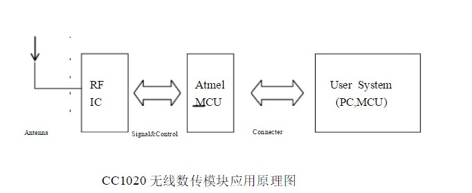
There are three kinds of interfaces, which can be directly connected with a computer, a single-chip microcomputer or other UART devices. The application diagram of cc1020 wireless data transmission module is as follows:
1. Power
CC1020 uses a DC power supply with a voltage of +3.0~5.0V. The power supply can be shared with other equipment, but please choose a power supply with a good ripple factor. If possible, use 7805 or other voltage stabilizers to supply power separately. In addition, if there are other devices in the system equipment, they must be grounded reliably. If there is no condition to reliably connect to the ground, it can form a ground on its own, but it must be completely isolated from the mains.
When working, the transmitting current is ≤33mA, the receiving current is ≤22mA, and the sleep power supply is ≤5uA.
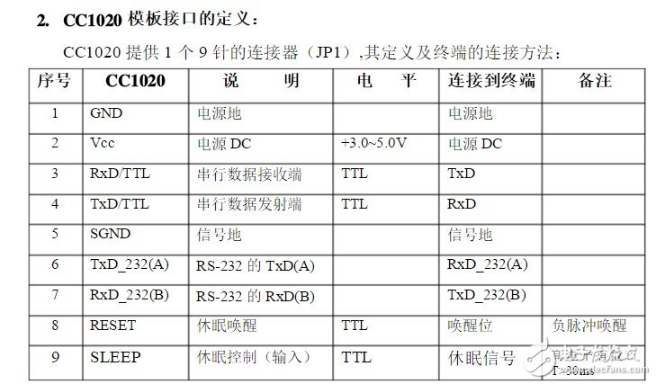
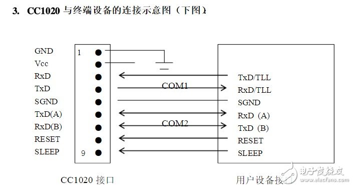
4. Channel, interface, data format setting:
Before users use CC1020, they need to perform simple configuration according to their own needs to determine the channel, interface mode and data format.
There is a set of 5-bit short jumpers (JP2) in the upper right corner of CC1020, which are defined as ABCDE respectively. Assuming that the jumper is open (without short-circuiter) in state 1, and jumper short-circuit (inserted by short-circuit device) is in state 0, the configuration method as follows:
four. The networking application of CC1020 wireless module and the matters needing attention in programming:
The communication channel of CC1020 is half-duplex, which is most suitable for point-to-multipoint communication. In this way, a master station must be set first, and the rest are slave stations. All stations have a unique address. The coordination of communication is completely controlled by the master station. The master station uses a data frame with an address code to send data or commands, and the slave stations receive all of them, and compare the received address code with the local address code. If they are different, all data will be discarded. Do any response; if the address code is the same, it proves that the data is for the local. The slave station will respond differently according to the data or command sent, and send the response data back. These tasks require upper-layer protocols to complete, and it can be ensured that at any instant, only one radio station in the communication network is in the transmitting state to avoid mutual interference.
CC1020 can also be used for point-to-point communication. It is simpler to use. When programming the serial port, just remember that it is a half-duplex communication mode and always pay attention to the timing of sending and receiving back and forth.
ConclusionThis is the end of the related introduction about CC1020. If you have any deficiencies, please correct me.
Related reading recommendations: CC1020-based wireless communication module design
Related reading recommendation: CC1020 chip introduction
16MM Metal Switches
Yeswitch 16MM Metal Switches could be divided into aluminum casing and stainless steel casing and also could be divided into Momentary Switch and self-locking Metal Push Button Switch .
This 16MM series Waterproof Push Button Switch offer a long life expectancy, could used in Industrial control instruments, Medical equipment, Security monitoring equipment, Vehicle peripherals, Audio-visual equipment and Energy storage equipment,etc.
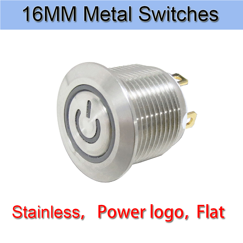
In addition, All casings are made through high-precision lathes, and the polishing and plating are rigorously screened. The metal fittings inside the metal switches are made of brass gold plated material, so the switch can have good conduction function and stable quality after long-term use.
The 16 series illuminated metal switches offer a long life expectancy, water resistance to IP67 ratings, and ring or power symbol illumination.This switch has a 16mm panel cutout size. Additional options include a high, high flat or rounded bezel option, and your choice of a solder lug or wire lead termination.
As for the indicator light , we offer customized service, customers could choose the effect , shape and the color. What is worth mentioning is that our indicator light could offer double color, which could offer our customers more choose in the item of light. Meanwhile, on the item of terminal shape, we could also offer customized service, we have solder terminal and free wire length could choose, 500mm is the normal standard.
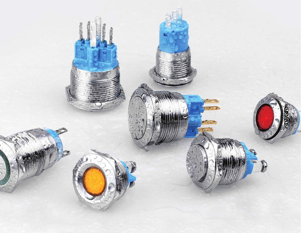
This serious metal Push Button Switches are of high quality and reliable products. The switch has passed IP67 dust proof and waterproof certification, which indicates it can be operated in harsh environments. Moreover, all materials could meet the European and American environmental protection requirements , for example, UL and ROHS certificate.
16Mm Metal Switches,Metal Push Button Switch Momentary,16Mm Momentary Metal Switch,16Mm Metal Push Button Switch
YESWITCH ELECTRONICS CO., LTD. , https://www.yeswitches.com
