Combine the Abaqus software to study the extrusion coating process of lithium ion battery manufacturing process
This article mainly introduces the extrusion coating process of lithium ion battery manufacturing process, and combines Abaqus software to study its coating process.
First, the basic introduction
First, extrusion coating type
With regard to extrusion coating, I understand that the fluid is coated on a moving substrate by extruding a coating head having a special flow path. The entire system is shown below (pictures from Quinones DM, Carvalho MD S. EFFECT OF DIE LIP CONFIGURATION ON THE OPERATING WINDOW OF SLOT COATING PROCESS [J]. Abcm.org.br, 2006.).
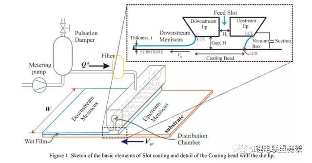
According to the distance between the coating head and the substrate and the formed fluid shape between the coating head and the substrate, it is divided into Slot Coating and Extrusion Coating, as shown in the following figure. . The difference between the two is mainly whether the fluid has a wet lip, the former wets the lip, and the latter does not. Lithium-ion power battery coating process uses a slit extrusion coating (Solt Coating).
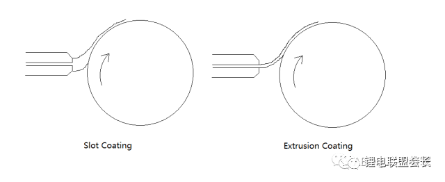
The difference between the two is mainly whether the fluid has a wet lip, the former wets the lip, and the latter does not. Lithium-ion power battery coating process using a slit extrusion coating (Solt Coating), coating system.
Second, the principle of slit extrusion coating
The two-dimensional schematic diagram of the flow distribution in the slit extrusion coating is as follows: The picture is from the article “Fundamentals of Slot Coating Process†by Prof. Marcio.

The factors that determine the coating quality mainly include the gap between the coating head and the base tape, the flow rate, the substrate speed, the structure of the coating head, and the characteristics of the fluid.
According to the parallel plate Eucute flow (see the fluid mechanics teaching resources of the Shanghai Jiaotong University Engineering Mechanics Teaching Base for further understanding) and Prof. Marcio's lubrication approximation model, the available thickness t formula is as follows:
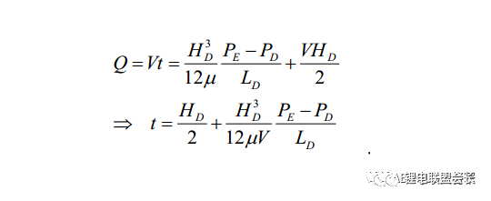
It can be seen that the coating thickness depends on the gap between the coating head and the base tape, the fluid viscosity, the substrate speed, the size of the coating head lip, the fluid, and the external pressure. It can be known from the formula that the gap between the coating head and the base belt is mechanically coordinated, the fluid viscosity is related to the incoming slurry, the substrate speed is the motor control, and the size of the coating head lip is determined by the coating head. The above factors are relatively easy to ensure consistent. The uniformity of the thickness of the applied coating is prominently manifested in the fluid and the external pressure, and the external pressure is generally the normal pressure in the room. Therefore, the uniformity of the pressure in and around the lip of the coating head becomes extremely important. The uniformity of the pressure distribution within the lip and the outlet of the coating head is closely related to the stability of the feed system and the structure of the coating head.
Second, the extrusion coating head structure introduced
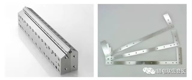
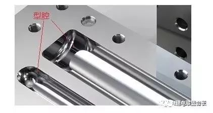
The coating head structure is actually relatively simple, mainly including the upper mold, the lower mold, and the gasket in three parts. The lower film has special cavities (such as gradient type, coat hanger type, single-chamber type and double-chamber type, etc.). The upper mold is relatively simple, and the gasket is located between the upper and lower molds, and can be selected according to different coating forms (eg zebra crossing , full coating, etc.). The figure below shows a coating head mold for Mitsubishi.
Second, slurry properties
First, the slurry composition
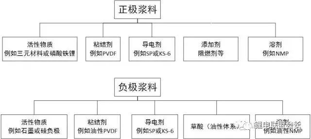
Lithium-ion power battery paste basically consists of active material, conductive agent, binder, and solvent. The general structure is shown in the figure below.
Second, the slurry properties
Slurry as the incoming material of the coating process, its characteristics directly affect the coating quality. By the slurry composition we can know that the slurry is a solid-liquid two-phase fluid. The production quality control points for the slurry mainly include viscosity, solid content, density, fineness, and pH. The uniform consistency of the slurry is crucial for the coating process. The uniform consistency of the slurry can be obtained by testing the quality control points of the slurry in different regions.
Since the viscosity of the slurry is related to temperature, stirring speed, settling time, etc., we define the slurry as a non-Newtonian fluid based on Newtonian and non-Newtonian fluid definitions. After the slurry is relatively evenly stirred, the viscosity of the slurry gradually decreases as the stirring time increases, and finally tends to a stable value. According to related literature, in the case of the lithium ion battery slurry in the state of homogenization and homogenization, there is a reduction in viscosity as the shear rate increases, ie shear thinning phenomenon. In summary, we attribute lithium-ion battery pastes to non-Newtonian fluids with shear thinning. Due to different materials, different mixing ratios, and different homogenization conditions, the fluid properties of the slurry vary under different conditions. This paper only describes the characteristics of the slurry fluid under universal and relatively uniform conditions.
Density Ï: Lithium battery slurry density is generally 1400 ~ 2000kg/m3
Viscosity μ: Lithium battery paste is generally controlled at 1~10 Pa·s according to different process conditions
Based on the above, we already know the structure of the coating head. Since this article is mainly concerned with the flow field state in the coating die, this article only establishes the flow channel liquid model.
Users can use third-party 3D software to model, and then export the stp or x_t universal format, and then import the Assembly geometry to import the slurry fluid geometry.
1) Create a geometric model
Create With CFD Model, then click File→Import→Aseembly and select the exported stp x_t file. (This article imports and selects Assembly but does not select Part, because importing shells occurs when you directly import Part.) Create the model as follows:
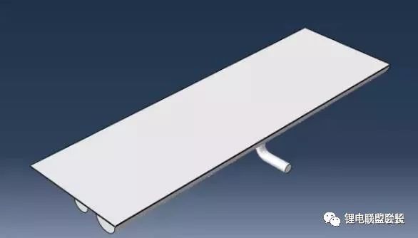
Axonometric
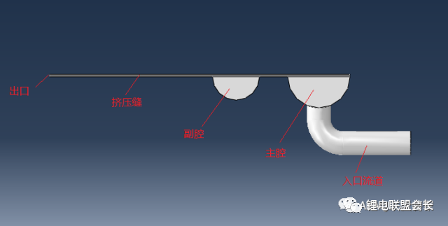
Side view
2) Create material properties
Since the model is established in this paper, the mm is used, and the unit is united to mm.
The slurry density was 1.7e-9 tone/mm3 and the viscosity was 1500 cps, ie, 1.5e-6 MPa·s. Assign the above material properties to the geometric model.
3) Create an assembly
Although the geometry model imported into the assembly, but the system identified as a component, you need to switch to the Assembly Model to create an assembly.
4) Divide the grid
In this paper, the segmentation tool can be used to segment the model, and the geometry is divided into hexahedral Hex meshes by using structured grids, sweep grids, and bottom-up grid partitioning. This paper uses the method to save grid partition time and calculation time. Tetrahedral Tet fluid cell FC3D4. The mesh density is controlled by the edge distribution. The meshing result is as follows:
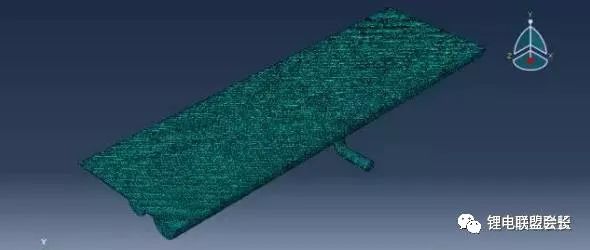
Meshing results
5) Create a fluid analysis step
Enter the Step Module and create a flow analysis step. Time Period: 1, Initial time increment: 0.001, Tubulence Model: None. The choice of time increment here depends on the quality of the mesh and the size of the payload. Considering that the viscosity of the slurry is large, the extrusion joint is narrow and the speed is small, the Renault model is not selected.
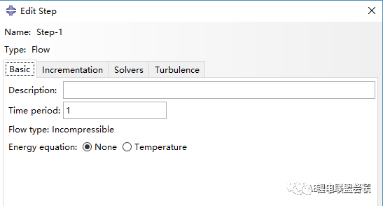
Edit Analysis Step dialog
6) Create boundary conditions and loads
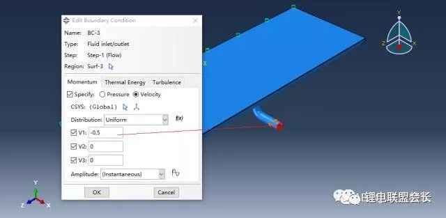
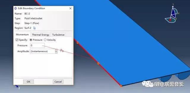
There are three main boundary conditions and loads. For specific operations, refer to the previous article “Abbreviated Knowledge and Cases of ABAQUS/CFDâ€.
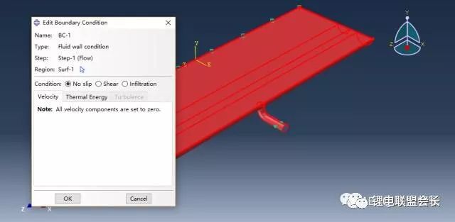
1 inlet speed boundary conditions, speed 0.5mm/s
2 outlet pressure boundary conditions, 0 MPa
3 fluids avoid boundary conditions, no sliding (outgoing inlets and outlets)
7) Create a task and submit it.
This step is the same as the previous case analysis step. After the task is submitted, the task operation monitoring can be performed. After finishing, click Result, automatically import the result of the operation and enter the Visualization Module.
8) Post-processing
The post-processing function allows you to see the pressure distribution in the flow field in the coating head
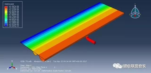
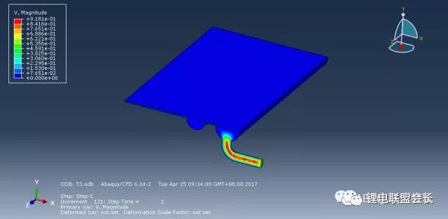
speed distribution
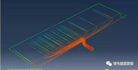
Through the Stream tool  , create pressure or speed streamline display effect chart,
The following shows the pressure streamline display.
Third, the coating flow field simulation analysis
In this section, the ABAQUS / Explicit CEL algorithm is used to simulate and analyze the coating flow field, and the process from coating initiation to stability is obtained. The user can view the effect of the feed rate, substrate speed, coating viscosity, etc. on the coating thickness according to the tutorial.
First, the slit extrusion coating model
With regard to the theoretical analysis of slit extrusion coating thickness, the user may refer to the article before the public number “Study on the Squeeze Coating of Lithium Ion Power Cells (1)—Basic Introductionâ€, and the article under the general public's name. "Resolving the Thermal Field of Squeeze-Squeeze Coating of Lithium-Ion Batteries", Quinones DM, Carvalho MD S. EFFECT OF DIE LIP CONFIGURATION ON THE OPERATING WINDOW OF SLOT COATING PROCESS [J]. Abcm.org. Br, 2006.â€, “Slit coating theory modeling and numerical simulationâ€, and extended literature. The two-dimensional schematic diagram of the slit extrusion coating is as follows:
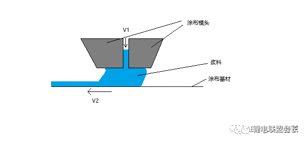
Second, Abaqus algorithm selection
The methods that Abaqus can perform for fluid analysis include CEL (Coupled Eulerian-Lagrangian) Euler coupling algorithm, CFD (Computational Fluid Dynamics) computational fluid dynamics, and SPH (Smooth Particale Hydrodynamics) smooth particle fluid dynamics. Regarding the scope of use and comparison of the three, the user can search "Comparison of CEL, CFD, and SPH in Abaqus" by Baidu search.
Both CEL and CFD use the fluid mesh material to flow through a fixed mesh node algorithm because the CEL can clearly show the free surface display of the fluid material, but Abaqus/CFD cannot, for example, the Abaqus CEL method. In addition, subsequent versions of Abaqus/CAE do not have a CFD module, and the CFD module is integrated into 3DEXPERIENCE r2017. I believe that the latter will improve its VOF model similar to FLUENT and can add fluid to the CFD module.
Third, Abaqus simulation application
1. Establish parts and assembly geometry models.
Create an Exolicit Model. Click to open Abaqus/CAE and select With Standard/Explicit Model.
Create the following Parts: Fluid Zone Geometry, Inlet Speed ​​Pusher, and Coated Substrate. Due to the inability to select continuous velocity feed conditions for the fluid material inlet under the CEL algorithm in the display kinetics analysis, this article will increase the inlet area and add a piston-like pusher block to provide velocity entry conditions. The assembly model is as follows:
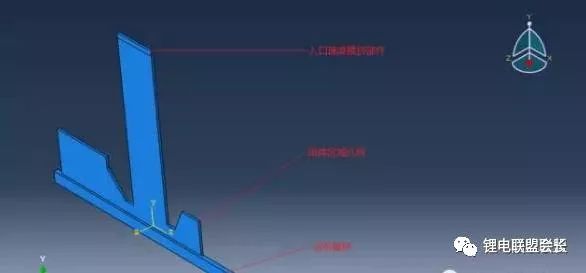
Remarks:
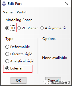
1) Due to the use of the CEL algorithm, the use of parts must be set to Eulerian type, and 3D must be selected as shown in the following figure.
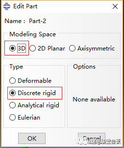
2) To simplify the model as 2D, we set the thickness of the component to 1 during the process of building the part. Other models are selected as discrete rigid bodies, as shown below
3) During the process of establishing the assembly, the discrete rigid body parts created cannot be directly added to the assembly. Select the rigid part under the Part Module and click Shape → Shell → From Solid from the menu bar to convert it into a shell.
4) Select the independent grid form during the creation of the assembly entity.
2, the establishment of material properties
The properties of the slurry material are established as the following three properties: Density, Viscosity, and eos (equations of state). In the Explicit model, the hydrodynamic material creation is performed with the help of the state equation Us-Up, as shown in the figure below.
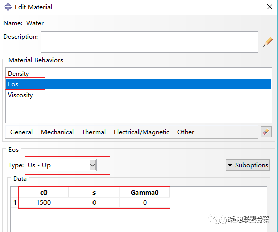
Other methods of using the equations of state and theory, the user can view Abaqus manual, the density is set to 1000, the face set to 5000. After creating the material, create the section properties and assign the interface properties to the fluid area geometry.
3. Create an analysis step and set the output result.
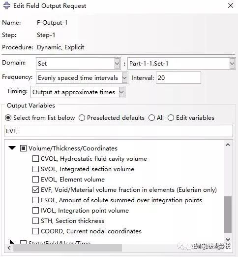
Switch to Step Module, create a new analysis step, display the dynamics, Time is set to 20s, the other remains unchanged, create the results as shown below.
Creates a geometric fractional EVF display of the fluid region, and the displacement output of the push block and component.
4, create contact characteristics and reference constraints
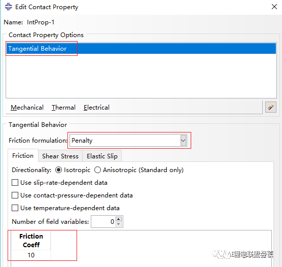
Establish the Tangential Behavior contact characteristic. The friction equation selects Penalty (penalty function) and the coefficient is set to 10. Because the material cannot establish the bonding properties between the material and the substrate, this paper selects the Penalty contact characteristics to establish the adhesion of the fluid material to the coated substrate. Related theory can be found in the Abaqus/CAE User's Guide under the Abaqus documentation.
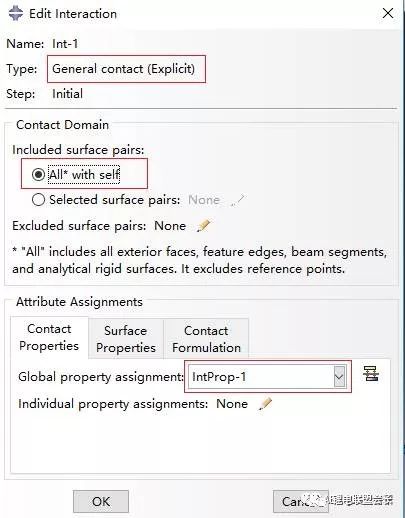
Establish contact surface from contact, as shown in the figure below
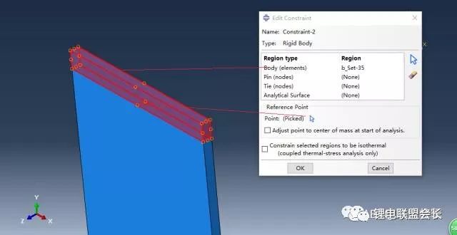
Create entry points to push test points for the part and establish point and part rigid constraints. As shown below. Similarly, establish reference points and rigid constraints for coated substrate parts.
5, meshing
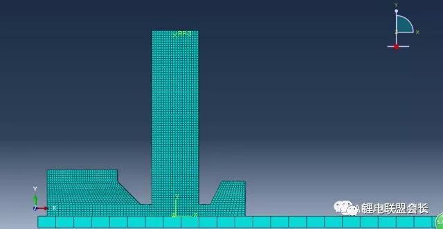
The segmentation tool is used to geometrically segment the geometric components of the fluid region so as to be able to use a structured mesh division method to perform mesh division by edge distribution. The result of the division is as follows. The mesh type of the fluid region geometry is: EC3D8R.
6, create a load and boundary conditions
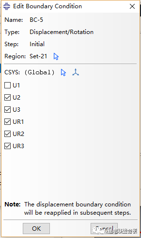
1) Create boundary conditions for coated substrates
Establish displacement constraints other than the direction of motion
Create speed boundary conditions for coated substrates
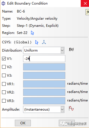
2) Similarly, create the entrance velocity to push the boundary conditions of the component and establish the boundary conditions of displacement constraint and velocity.
Speed ​​boundary conditions are as follows
3) Create boundary conditions for fluid area geometry.
Set the initial speed boundary of the Z direction inside and outside the Z direction
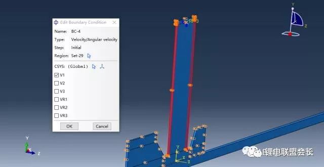
Set the initial speed boundary in the X direction on both sides of the entrance, as shown in the following figure
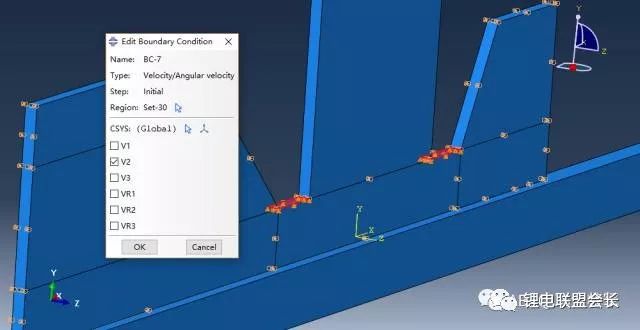
Set the initial speed boundary condition in the Y direction at the outlet of the coating head, as shown in the following figure
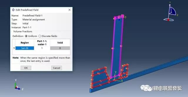
4) Create a predefined field Material assignment, the pink area is the initial fluid fill area, Void is zero, indicating that the material is completely filled.
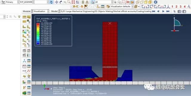
7, create analysis tasks, submit, and post-processing.
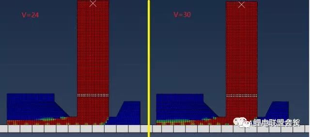
Create the task, and after submitting, view the EVF, Void/Material volume fraction in element (Eulerrian). Click on the cloud to display it. The result is as follows. The red area is fluid.
Users can view and compare conditions such as changing the material and substrate speed. The figure below shows a comparison of the effects of 24 and 30 substrate speeds.
With more than 15+ yrs rich MFG experience, you can definitely trust in and cooperate with.
Provide you with the supply of Personal Protective Equipment. to help you safely get back to your daily routine.
Our products include pulse Oximeter Finger, Forehead Thermometer, Automatic foam soap dispenser, etc.
Our strict quality control protocol thoroughly vets every aspect of production, storage, and shipments all the way way to our end customers.
infrared thermometers wholesale, forehead thermometer wholesale,wholesale thermometer suppliers
TOPNOTCH INTERNATIONAL GROUP LIMITED , https://www.itopnoobluetoothes.com
