A controller architecture for automatic drift of complex trajectories
The ability to maneuver outside the stable control range is important to the overall safety and robustness of an autonomous vehicle. Therefore, this paper proposes a controller architecture for automatic drift of complex trajectories. A controller for a non-specific path is designed without assuming that the vehicle operates near the equilibrium point. A physically meaningful control law is proposed: the vehicle heading angular velocity is used to track the path, and the yaw angular acceleration is used to stabilize the side-slip angle of the center of mass. Through the combination of nonlinear model inversion and lower wheel speed control, the required state differentiation can be accurately realized under a wide range of operating conditions. Real-vehicle tests on full-scale vehicles show that trajectories can be tracked well under different curvatures, velocities, and center-of-mass slip angles.
Separate lateral/longitudinal controls are typically employed in conventional vehicle control architectures, and the vehicle is assumed to be within the dynamic stability range for side slip. However, strong input coupling and yaw/slip instability beyond the vehicle's handling limits render this simplified approach ineffective. A professional driver can achieve precise control of both the vehicle's sideslip and the driving path while drifting, albeit completely outside the vehicle's stability limits. Autonomous driving drift control algorithms can extend the vehicle's available state space beyond the limits, thereby ensuring the widest range of maneuvering for autonomous vehicles.
In the early literature, Velenis [9] and Hindiyeh et al. [4] studied the stabilization of the vehicle state at the drift equilibrium point through simulation and experiment, respectively. Since the system is underactuated at standard inputs (rotation angle and drive torque), it is not straightforward to track the path and stabilize the center of mass slip angle at the same time.
Several recent studies have demonstrated this in a simple fixed-circle test. The controller proposed by Werling et al. [11] considers both centroid slip angle stabilization and path tracking, while the strategy of Goh et al. [3] is to explicitly track the path. However, these methods cannot be easily extended to more complex trajectories due to strict assumptions made in vehicle modeling and controller design.
In the literature, drift studies have used accurate vehicle models over a wide range. Ono [6] and Voser et al. [10] used a two-state monorail model to study the unstable dynamics of drift. A three-state monorail model with force as a direct input [3] [4] and accurate modeling of steering and throttle delays [11] is also used to experimentally verify the design of the controller. Velenis et al. [9] designed a linear quadratic regulator based on a linearized two-rail vehicle model with steady-state load transfer and wheel dynamics. A balance between model accuracy and controllability of the equations of motion remains to be studied further.
Compared with these methods, this paper designs an automatic drift controller for handling complex trajectory conditions. The center of mass slip angle error and lateral displacement error in the road curve coordinate system are used as control targets. The dynamics model required for controller design is first derived without assuming a specific vehicle model or vehicle state near the equilibrium point. The resulting control law, represented by the vehicle state differential, is very simple and intuitive. Using the dynamic decoupling of sideslip and yaw during drifting: the vehicle yaw angular velocity is directly used to track the path, and the center of mass sideslip angle can be stabilized at the same time by controlling the speed of the vehicle yaw angular velocity relative to the yaw angular velocity.
To implement this control law, the vehicle model is required to map these desired state differentials to inputs. The combination of nonlinear model inversion and lower-level wheel speed control achieves good accuracy for a wide range of operating conditions under complex trajectories, rather than relying on oversimplified assumptions. Experiments on a full-scale test vehicle, MARTY (Fig. 1), validate the algorithm for trajectories with curvature varying from 1/7 to 1/20 m and velocities varying from 25 km/h to 45 km/h, as well as -40° centroid sideslip Validity in angular conditions.
Figure 1 MARTY vehicle in automatic drift test
2 Test Vehicles and Vehicle Models
This section first introduces the motion equations of the force input-based monorail model in the curvilinear coordinate system, and then introduces the tire force model.
2.1 Equations of motion
2.1.1 Path following states and dynamics
The vehicle model is shown in Figure 2 with three state variables: the yaw rate r, the velocity V and the center of mass slip angle β. After considering path tracing, several other state variables are introduced. The vehicle heading angle is the direction of the vehicle velocity vector in a given inertial coordinate system, the dynamic equation:

Figure 2 The three-state monorail model in the reference path curve coordinate system
Using a curvilinear coordinate system to make the vehicle track the reference trajectory, the lateral displacement error e is the distance from the center of mass of the vehicle to the closest point on the reference trajectory, and s is the distance along the path to this point. The reference heading angle is the tangent angle of the path at s relative to the inertial coordinate system, and the heading angle error , is the difference between the vehicle heading angle and the reference heading angle. The kinetic equation of e is expressed as:

Make some simplifying assumptions: 
 and
and , due to the closed-loop control
 gradually becomes smaller, so the assumption is reasonable.
At last, The kinetic equation of is

in is the curvature of the reference trajectory at s.
2.1.2 Vehicle state and dynamics
The nonlinear vehicle model inversion is performed based on the monorail bicycle model shown in Figure 2. The forces acting on the vehicle include the front axle lateral force Fyf, the rear axle lateral force Fyr and the rear axle longitudinal force Fxr. The equation of motion is:
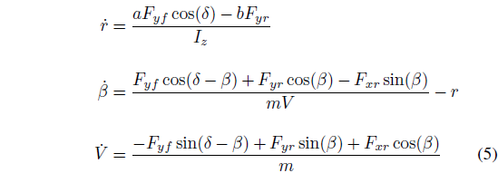
where δ is the steering angle, a and b are the distances from the front and rear axles to the center of mass, respectively, and m is the vehicle mass.
2.2 Front axle tire force modeling
The front axle lateral force Fyf is represented by the Fiala brush tire model [2], which is also used in the drift controller in [3] [4].

where Fz is the tire vertical load, Cα is the cornering stiffness, α is the cornering angle, and μ is the tire adhesion coefficient.
2.3 Rear axle tire force modeling
When drifting, the entire rear tire contact patch is completely slippery. Assuming an isotropic friction coefficient, the lateral and longitudinal forces are constrained by the friction circle relationship:

Reference [3] [4] In the design of the control algorithm, the expected rear axle lateral force Fyf and the rear axle longitudinal force Fxr are established through the friction circle, and the rear axle longitudinal force is directly used as the system input and multiplied by the tire radius to obtain the rear axle rotation. moment demand.
This method ignores wheel dynamics, which are quite important when considering more complex trajectory conditions; Fxr is not the real input, but the result of tire and road slip. For a fully saturated tire, the force-slip relationship can be modeled in a way that is both simple and physically meaningful: the force is of magnitude μFz in the opposite direction to the slip velocity vector Vslip. This direction is defined as the thrust angle γ, as shown in Figure 3, changing the length of the Rω vector can directly change γ. The geometric relationship is:

where R is the tire radius, ω is the wheel speed, and Vtravelx and Vtravely are the longitudinal and lateral components of the vehicle's speed at the tire, respectively.
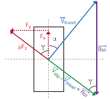
Figure 3. Velocity and force vectors of skid steer tires
It is worth noting that in the fully saturated state, this relationship is consistent with the expression of the brush tire model [7] and the simplified magic formula tire model [1]. The control input of the system, expressed in wheel dynamics ω as:

where Iω is the moment of inertia of the wheel-tire-drive system, and τ is the actual torque.
3 Controller Design
3.1 Overview
The task of the controller is to track a given path and desired center of mass slip angle using steering angle and rear axle drive torque. Therefore, the lateral displacement error e and the centroid slip angle β are selected as control variables.
The overall structure of the controller is shown in Figure 4. In the first part, the desired heading angular velocity is obtained based on the desired stabilization dynamics of e and β and the integrated yaw rate rsyn, the desired yaw acceleration is obtained by closing the loop on rsyn
 .
.
In the second part, the nonlinear vehicle dynamics model inversion will and
and This translates into the steering angle δ and the desired thrust angle γdes. The thrust angle is then mapped to the desired wheel speed ωdes. Finally, the driving torque τ is obtained by closing the loop for ωdes.
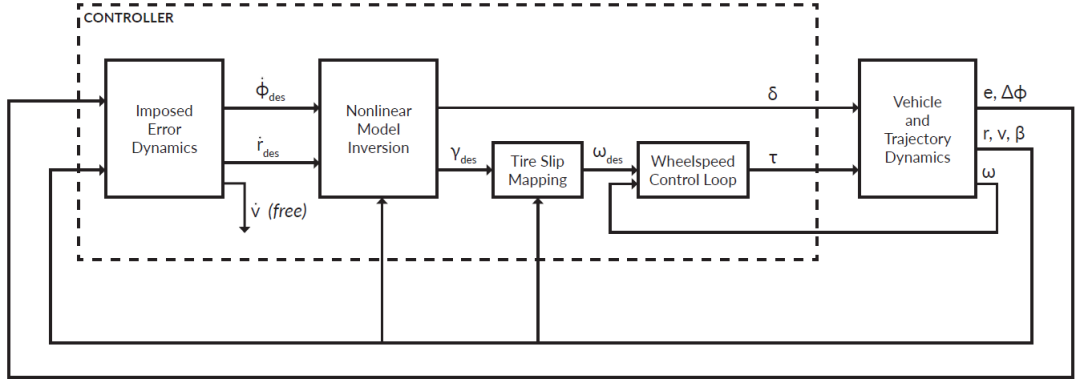
Figure 4 Controller Architecture Block Diagram
3.2 Error dynamics
3.2.1 Path Tracing
heading angular velocity Used directly for tracing paths. The expected second-order kinetic equation for the lateral displacement error e is:
 get the expected
 :
:

3.2.2 Stabilized centroid slip angle
Then, with The associated vehicle yaw rate, used to stabilize the center of mass slip angle. Centroid Slip Angle Tracking Error
 The expected first-order kinetic equation of :

Similar to the method in [3] [4], the expected yaw rate rsyn is calculated based on the comprehensive input , these methods carried out
 The steady-state approximation of , then, due to the
 With explicit control, use the desired heading rate
 alternative.

Tracking error for yaw rate The first-order derivative of , obtains the desired yaw angular acceleration
 .
.

in is the derivative of the comprehensive yaw angular velocity, which can be approximately expressed as:

in is the yaw acceleration of the reference trajectory.
3.3 Nonlinear Model Inversion
Through the inversion of the nonlinear monorail vehicle model in Eq. (5), the expected Converted to steering angle and rear axle longitudinal force/thrust angle.
Figure 5 is a set of representative surface relationships between state differentials. projected to Plane (Figure 6), it can be seen that the surface is folded, that is, the partial region has two solutions for a given combination. This divides the surface into a larger "upper" surface and a smaller "lower" surface; the dividing line is shown by the red line in Figures 5, 6, and 7.
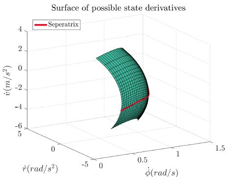
Fig.5 3D diagram of vehicle state differentials when the yaw rate is 53.9°/s, the vehicle speed is 9.35m/s, and the center of mass slip angle is -40°
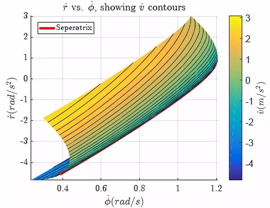
Figure 6 Yaw angular acceleration vs heading angular velocity along the vehicle speed differential contour

Figure 7. Yaw velocity vs vehicle speed differential along the yaw acceleration contour
Usually, only a small The space is located on the lower surface, so the model inversion can get a 1-to-1 mapping relationship under the upper surface constraints and ensure the continuity of the actuator instructions in a simple way. Also of note is that the upper surface often includes state combinations
 , as shown in Figure 7, this state differential space can be achieved when tracking a quasi-equilibrium trajectory.
demand It is possible to fall outside the feasible region. Simple handling of this situation arising from the initial moment in the controller and in the experiment.
 value of
 saturation constraints for the feasible region, then compute
 . owned
 along
along Lines are projected into the feasible region. The unstable yaw/yaw dynamics control in the proposed strategy has priority over the lateral displacement error control.
3.4 Wheel speed control
According to the longitudinal force/thrust angle of the rear axle obtained by inversion of the nonlinear model, the expected wheel speed is obtained according to the force-slip relationship in formula (8). The desired wheel speed ωdes is tracked based on simplified dynamic surface control [3].

in is the desired wheel speed at a time constant of
 obtained after first-order filtering of , using the desired rear axle longitudinal force
 Calculate the feedforward torque.
Because the rear wheels of the MARTY test vehicle are independently controllable and mechanically decoupled, the left and right rear wheels are controlled separately. Let the thrust angles of the left and right rear wheels be , get the desired left and right wheel and right rear wheel speeds
 and
and , where d is the wheelbase of the vehicle, and the expected longitudinal force of a single wheel is obtained based on the assumption of steady-state load transfer:

in is the empirical value of load transfer occurring at the rear axle, h is the height of the center of mass.
4 Test verification
The effectiveness of the algorithm is verified by experiments on complex trajectories with curvature varying from 1/7 to 1/20 and speed varying from 25km/h to 45km/h and a reference center-of-mass slip angle of -40°.
4.1 Test method
The test was carried out on the test platform MARTY as shown in Figure 1. Converted from a 1981 DMC Delorean, the MARTY features controlled-by-wire steering and an electric drive system that drives the left and right rear wheels independently. The vehicle status information is obtained through the integrated RTK-GPS/IMU, and the update frequency is 250Hz. The operation frequency of the control algorithm running in real time on the upper computer is also 250Hz.
Simple entry and exit loops are added at the start and end of the reference trajectory, respectively, and a basic path tracking controller similar to that used in [5] makes the vehicle track this path. The drift controller stepped in at s=57m and exited at s=463m. The controller parameters and vehicle parameters are shown in Table 1.
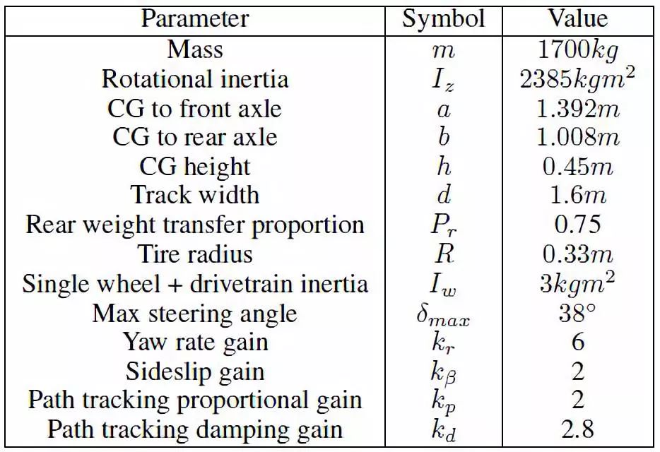
Table 1 Controller parameters and vehicle parameters
4.2 Trajectory Planning
In the method of Reference [5], the trajectory is composed of a sequence of unstable drifting equilibrium points. First, choose the desired curvature and centroid slip angle
 , which is a function of the path distance s. For each point in the reference trajectory, set
 and
and Substitute into the equation of motion to solve the reference trajectory
 value, with reference to the centroid slip angle
 Approximately expressed as
 .
.
The curvature of the selected profile varies from 1/7 to 1/20 m, and the reference center of mass slip angle is -40°, resulting in trajectories with equilibrium velocities between 25 km/h and 45 km/h.
Figure 8 Track curvature and reference centroid sideslip configuration
4.3 Test results
The control algorithm tracks the reference trajectory well and shows good tracking effect of lateral displacement error and centroid sideslip angle.
As shown in Figure 9, the actual path of the vehicle is very close to the reference path, and Figure 10 shows the relationship between the lateral displacement error and the path distance: the root mean square error is 0.18m, and the maximum deviation is -0.36m.
The above-mentioned good path tracking performance is achieved when the vehicle is in a state near the desired center of mass slip angle of -40°. Figure 11 shows the measured vehicle state, and it can be seen that the center of mass sideslip angle tracking effect is good: the root mean square error is 2.4°, and the maximum deviation is only -6.1°. The speed under the closed loop is also very close to the trajectory reference speed, which not only shows that the vehicle speed is stable, but also shows that the model used for planning is more accurate. The measured yaw rate can also track the reference yaw rate well, except at the beginning of the drift.
Finally, it is worth noting that because the nonlinear model inversion is performed over a larger range of states, a larger range of inputs is generated - the most obvious example being the control algorithm reaching 65° when tested in Figure 6.
Figure 9 Measured path vs reference path in experiment
Figure 10 Path tracking performance in the test
Figure 11 Vehicle state vs path distance in the test
Figure 12 Steering angle and thrust angle input in the test
5 Conclusion
In this paper, an autonomous driving drift controller for complex trajectories is designed. The controller is derived from vehicle state differentiation and does not involve a specific vehicle model. The yaw angular velocity is used to track the lateral displacement error in the curvilinear coordinate system, and then control the yaw angular velocity relative to the yaw angular velocity to control the center of mass slip angle.
In order to obtain the mapping relationship between vehicle state differential and actuator input, nonlinear model inversion and simple wheel speed closed-loop control are performed. Experiments demonstrate the effectiveness in complex trajectories with curvature varying from 1/7 to 1/20 and speed varying from 25 km/h to 45 km/h, and a reference center-of-mass slip angle of -40°.
Research on path tracking and center-of-mass sideslip stabilization of drift equilibrium points under complex trajectories ensures that autonomous vehicles can maneuver beyond the open-loop stability limit when required. Future research will further consider implementing trajectory planning and tracking without quasi-equilibrium assumptions to address the problem of rapidly changing vehicle states.
Wuxi Doton Power , http://www.dotonpower.com
